

|

|

|

|

|

|

|

|

|

|

|

|

|

|

|

|

|

|

|

|

|

|

|

|

|

|

|

|

|

|
PA UT (PAUT): Glass Fiber


The following features are provided:
- Scanning Pattern (Scan Plan) Design
- Intuitive Image Guided PA Pulser Receiver with Beam Forming View
- True-To-Geometry 0-deg Cross-Sectional Coverage of the material and line scanning along the part either encoded or time based
- "On-the-fly" True-To-Geometry Material Overlay Volume Corrected Imaging:
- Cross Sectional Slices
- Top (C-Scan) View
- Side View
- End View
- 3D View
- DAC / TCG Data / Image Normalization
- Independent on TCG Angle Gain Per Focal Law Correction
- 100% Raw Data Capturing
- Automatic Defects Alarming Upon C-Scan Acquisition Completed
- Automatic Creation of Editable Defects List
- Comprehensive Postrpocessing Toolkit Including:
- Recovery and Evaluation of the Captured A-Scans from the Recorded Cross Sectional Views and C-Scans
- Recovery of the Cross Sectional Views from the Recorded C-Scans
- Converting Recorded C-Scans or their Segments into 3D Images
- Off-Line Gain Manipulation
- Off-Line DAC Normalization of the Recorded Images / DAC Evaluation
- Numerous Filtering / Reject Options ( by Geometry / Position / By Amplitude db-toDAC / etc ) and Regeneration of the Corresponding of Editable Defects List and Storing it into a Separate FIle
- Defects Sizing
- Automatic creating of inspection reports - hard copy / PDF File
|

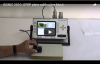
The movie below illustrates the scanning of GFRP panel calibration block with flat bottom holes, the operator's observations and the evelauation at the postprocessing stage
The videos below illustrate 0-deg compression wave scaning of the GFRP panel using the water filled rolling probe with soft silicon tire and linear array probe with solid delay line
The video below illustrates inspection of the GFRP made components of various aircraft and high speed trains frames, wind turbibe blades, etc
Another typical case related to the inspection of GFRP panel made through the bonding between two plates (for example � composite repair) has been illustrated by the video below, which shows the ability of detecting de-bonding between the plates and internal defects in both plates as well. The internal defects are detectable through the scanning above the plate carrying them as well as from the opposite side
The next video shows detection of the impact damages in the performance demonstration block made by the asset owner for the high speed automatic inspection of large diameter GFRP tubes using ISONIC PA AUT platfrom module carrying the ability of performing high productivity inspection using up to 4 PA probes simultaneously
At last the short movies below illustrate detection of the artificial refelectros imitating laminations in the GFRP calibration block using ISONIC 3510, ISONIC 2010, and ISONIC 2009 UPA Scope instruments
Note: In order to accelerate the data stream the videos above are linked to the Youtube. In case the YouTube may not be accessed from your location please use the link below

|

|

|
|

|
|
|
|

|
|
|
|
DOWNLOAD AND PLAYBACK THE EXEMPLARY INSTRUMENTS FILES
|
