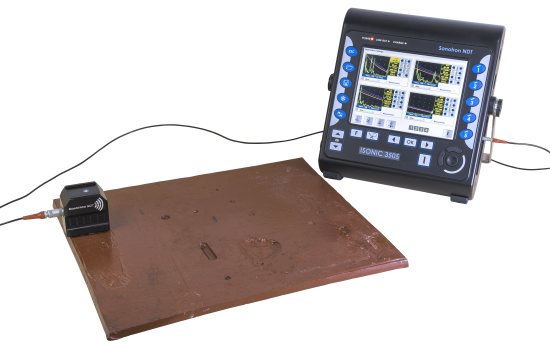
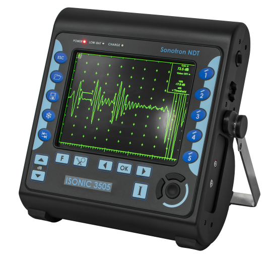
ISONIC 3505 carries the exceptionally innovative ultrasonic card with never-saturated-receiver ñ for the first time ever the instrument keeps the linearity over 140 dB dynamic range
digitizing the originally received signals independently on the gain and rectification settings in every firing / receiving cycle. Once the single A-Scan or the sequence of A-Scans forming a record is stored
into a file it may be reproduced off-line in the form desired by an operator (RF, half- or full wave rectified, FFT) at any gain level over the 140 dB range. So even in case of very significant deviation of
the pre-inspection gain setting from the required one the observation and evaluation of the recorded data may be performed at the right levels without secondary scanning
The top level ultrasonic performance of ISONIC 3505 is achieved thanks to the above noted never-saturated-receiver and to the versatile firing circuit allowing forming of either
Spike, Unipolar-, or Bipolar Square Wave initial pulse with wide-range-tunable duration and amplitude (up to 400 Vpp). The high stability of the square wave initial pulse amplitude within entire duration of
the positive and negative half-waves, the extremely short boosted rising and falling edges and the automatic adaptive damping allows optimizing of the ultrasonic wave penetration into various materials characterized either by high
or low grain size, sound attenuation, and the like and improving of the signal to noise and the resolution
As itís predecessor ISONIC 2005 (also known as ISONIC 2020 in the South East Asia and ISONIC STAR in China), which became one of the most popular instruments across the
world with over decade market life, ISONIC 3505 may be operated as:
superior performance A-Scan set including the spectrum analyzer for ultrasonic signals
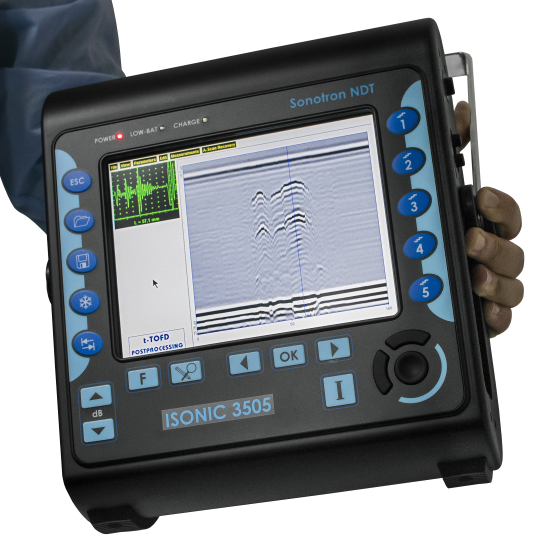
fully featured (data capturing and enhanced postprocessing) standalone TOFD unit
CHIME system
general purpose CB-Scan machine for the performing of:
SRGW (short range guided wave) inspection and imaging also known as SRUT
surface / shear wave inspection and mapping
volume overlay incidence angle / skip corrected high resolution flaw detection B-Scan and Thickness Profile recorder
C-Scan through raster scanning with straight- and angle beam probes either mechanic-free or with use of the mechanized or automatic XY scanner (optional)
with 100% raw data storage
Thanks to the never-saturated-receiver ISONIC 3505 is featured with the ability of individual gain control for both independent gates over the range of 140 dB separately from the rest of the A-Scan
reproduced at the global instrument gain. This opens a number of new abilities such as:
implementing pulse echo and back echo attenuation inspections simultaneously with use of the same A-Scan whilst monitoring the back echo amplitude at the clearly visible level
without affecting the sensitivity of the pulse echo inspection
increasing the detectability of subsurface defects for TOFD inspection through shortening the tail of lateral wave signal dynamically
precise materials characterization through the signal spectrum analysis independent on the instrument gain setting
etc
ISONIC 3505 is fully controllable over Ethernet and featured with the hardware triggering in/out terminals and the interface echo triggering making it suitable for use in various integrated systems
The lifetime free software upgrade policy is provided for ISONIC 3505 as for all other instruments from Sonotron NDT
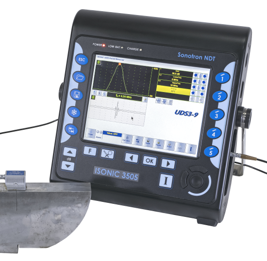
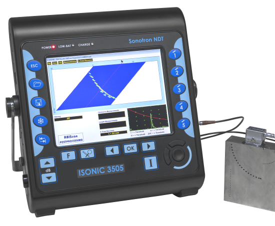
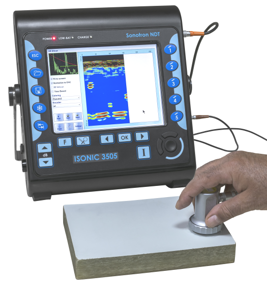
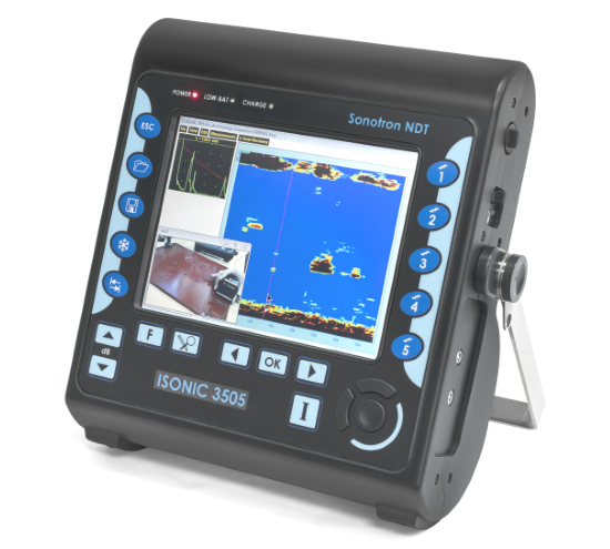
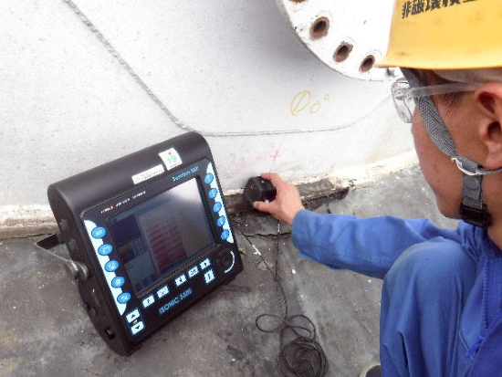
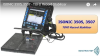
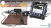
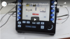
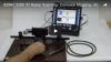
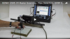
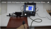
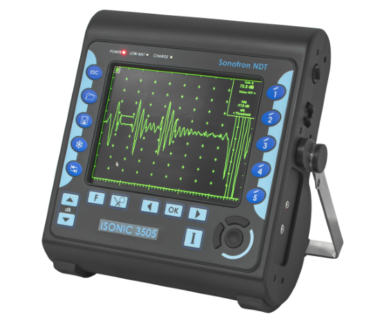
ISONIC 3505 is packed into the IP 65 reinforced plastic case with no intake air or any other cooling means. The large 800X600 8.5î bright screen provides fine resolution and visibility for all types of inspection
data presentation at strong ambient light along with the optimized power consumption rate for the outdoor operation
Ultrasonic Pulsing / Receiving:
Versatile Pulser with the Booster of the Rising and Falling Edges of the Initial Pulse and the Automatic Adaptive Damping ñ Switchable Pulsing Modes:
Spike Pulse
Unipolar Square Wave Initial Pulse with boosted rising and falling edges and guaranteed mark level stability and active damping
Bipolar Square Wave Initial Pulse with boosted rising and falling edges and guaranteed mark level stability and active damping
Smoothly Tunable Amplitude (14 Levels)
Smoothly Tunable Duration
10 Grades of Automatic Adaptive Active Damping
Wide Band 140 dB Dynamic Range Never-Saturated Receiver
Digitizing of the Originally Received Signals over Entire 140 dB Dynamic Range Independently on Gain and Rectification Settings
Comprehensive postprocessing and data reporting toolkit
Remote control and data capturing with use of a regular PC with no need in special software
No intake air / no cooling IP 65 light rugged case
Sealed all-functional keyboard and mouse
8.5î bright touch screen
Ethernet, USB, sVGA terminals
VAUT
GPS
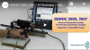
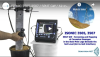
ISONIC 3505 is fully compliant with the following codes
ASME Section I ñ Rules for Construction of Power Boilers
ASME Section VIII, Division 1 ñ Rules for Construction of Pressure Vessels
ASME Section VIII, Division 2 ñ Rules for Construction of Pressure Vessels. Alternative Rules
ASME Section VIII Article KE-3 ñ Examination of Welds and Acceptance Criteria
ASME Code Case 2235 Rev 9 ñ Use of Ultrasonic Examination in Lieu of Radiography
Non-Destructive Examination of Welded Joints ñ Ultrasonic Examination of Welded Joints. ñ British and European Standard BS EN 1714:1998
Non-Destructive Examination of Welds ñ Ultrasonic Examination ñ Characterization of Indications in Welds. ñ British and European Standard BS EN 1713:1998
Calibration and Setting-Up of the Ultrasonic Time of Flight Diffraction (TOFD) Technique for the Detection, Location and Sizing of Flaws. ñ British Standard BS 7706:1993
WI 00121377, Welding ñ Use Of Time-Of-Flight Diffraction Technique (TOFD) For Testing Of Welds. ñ European Committee for Standardization ñ Document # CEN/TC 121/SC 5/WG 2 N 146, issued Feb, 12, 2003
ASTM E 2373 ñ 04 ñ Standard Practice for Use of the Ultrasonic Time of Flight Diffraction (TOFD) Technique
Non-destructive testing of welds - Ultrasonic testing - Use of time-of-flight diffraction technique (TOFD). - International Standard EN ISO 10863:2011
Non-Destructive Testing ñ Ultrasonic Examination ñ Part 5: Characterization and Sizing of Discontinuities. ñ British and European Standard BS EN 583-5:2001
Non-Destructive Testing ñ Ultrasonic Examination ñ Part 2: Sensitivity and Range Setting. ñ British and European Standard BS EN 583-2:2001
AD 2000-Merkblatt HP 5/3 Anlage 1:2015-04: Zerstˆrungsfreie Pr¸fung der Schweiþverbindungen - Verfahrenstechnische Mindestanforderungen f¸r die zerstˆrungsfreien Pr¸fverfahren - Non-destructive
testing of welded joints ñ Minimum technical procedure requirements for non-destructive testing methods (Germany)
ISONIC 3505 LF is the modified version of ISONIC 3505 adopted for the low frequency ultrasound applications. It is characterized by the appropriately modified frequency band of the receiver and the limits for manipulating duration of
the initial pulse ñ refer to Technical Data
ISONIC 3505 LF is suitable for the inspection of highly attenuating materials such as concrete, fiberglass, rubber, special purposes composites and other materials, etc. The upper limit of the frequency band keeps the opportunity for the
inspection of metals and the like
The zero point test and annual verification procedures of ISONIC 3505 and ISONIC 3505 LF are fully compliant with the international standards below and the corresponding national norms
EN 12668-1 / ISO 22232-1. Non-destructive testing ñ Characterization and verification of ultrasonic examination equipment. Part 1: Instruments
EN 12668-3 / ISO 22232-3. Non-destructive testing ñ Characterization and verification of ultrasonic examination equipment. Part 3: Combined Equipment
Ultrasound Velocity and Probe Delay Auto-Calibration for the Probes of All Types
Freeze A-Scan:
Freeze All
Freeze Peak
Note: Signal Evaluation, Manipulating of the Global Gain over - 30 ... +110 dB Range, Gates Positions and Gain per Gate over - 30 ... +110 dB Range and Signal Presentation Settings (Display Mode) is Possible for the Frozen A-Scans
From an external computer running under W'XP, W'7, W'8, W'10, W'11 through Ethernet or Wi Fi
From 3,4,5G Cell Phone
No special software required
All calibration and inspection data is stored in the control computer
Ambient Temperature:
-30∞C ... +60∞C (operation)
-50∞C ... +60∞C (storage)
Housing:
Rugged reinforced plastic case with the stainless steel carrying handle / MIL-STD-810H 516,8 applicable tests passed
IP 65
No air intake
The cooling is not required
Dimensions:
292x295x115 mm (11.50"x11.61"x4.53") - with / without battery inside
Weight:
4,400 kg (9.70 lbs) ñ with battery 3.750 kg (8.27 lbs) ñ without battery
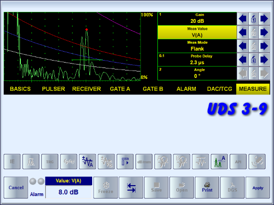
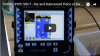
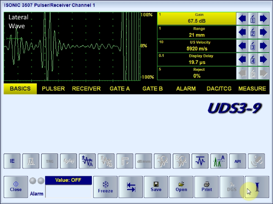
A-Scan - Time Domain Signal Presentation
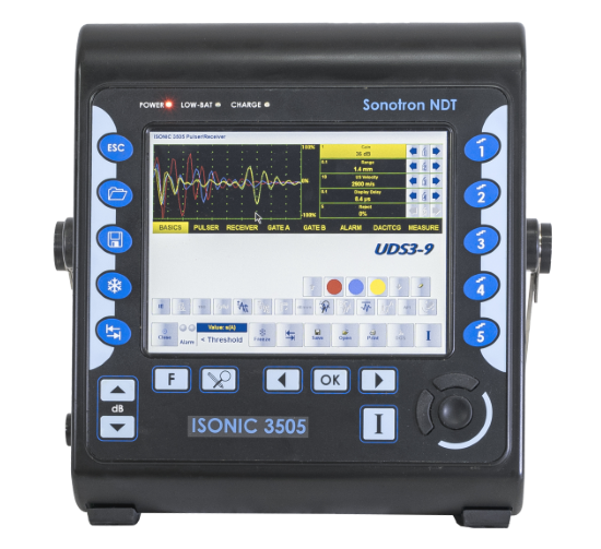
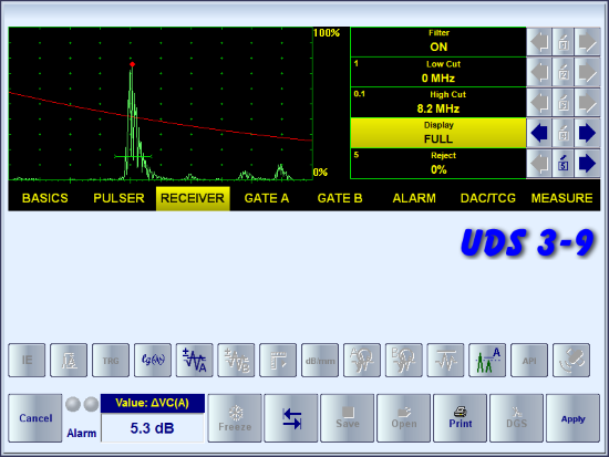
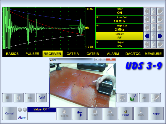
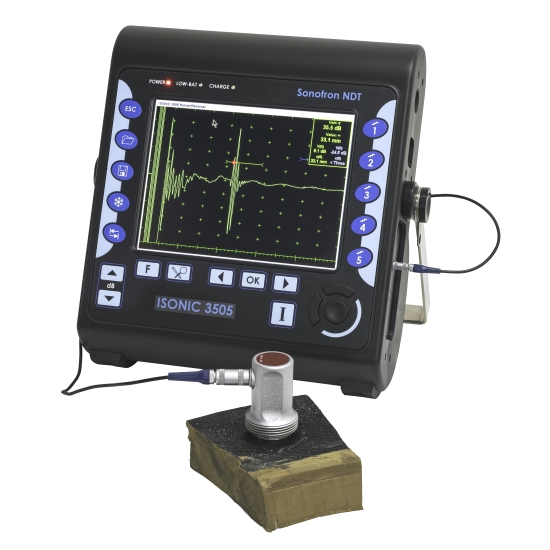
UDS 3-9 Pulser Reciever provides the top level A-Scan ultrasonic flaw detector functionality of ISONIC 3505. In the instrument it is used for the various pure A-Scan based inspections and
for calibration purposes prior to the inspections performed with the data recording through either Line- or Raster- scanning
Thanks to the ability of generating the spike, the unipolar, and the bipolar square wave initial pulse ISONIC 3505 is suitable for the resolving of the widest variety of ultrasonic inspection
tasks. The amplitude of the initial pulse is smoothly tunable for all generated shapes ñ there are 14 possible grades of Firing Level; the maximal grade (14) corresponds to 200 V amplitude of the unipolar
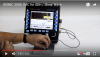
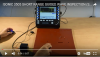
initial pulse / 400 Vpp amplitude of the bipolar initial pulse. The instrument screen movie below taken with no probe connected illustrates the possible shapes of the initial pulse and manipulations related
to the settling of the pulse width and firing level
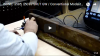
The signals received from the material may be optimized significantly whilst resolving certain inspection tasks with use of suitable probes - for that purpose
ISONIC 3505 carries the ability of selecting most suitable shape of the initial pulse and tuning it's width and firing level accordingly; the instrument screen movie below illustrates the influence
of the shape of the initial pulse and the pulse width settings on the echo amplitude, signal-to-noise ratio, etc
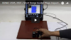
There are 10 grades for the active damping of the initial pulse available; varying damping allows shortening of the echoes received from the material without affecting their amplitudes - the instrument screen movie
below illustrates an example of the same
Note: In order to accelerate the data stream the videos above are linked to the Youtube. In case the YouTube may not be accessed from your location please use the links below
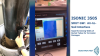
The receiver of ISONIC 3505 keeps the linearity over 140 dB dynamic range and digitizes the actual waveform of the signal independently on the way it is displayed on the screen. These unique
features of the instrument are illustrated by the videos below
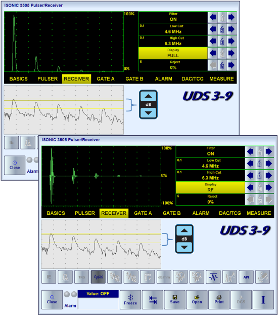
The types of the time domain signal presentation. Independently on the time base and DAC and TCG settings it may be toggled between:
RF ñ not rectified; represents the actual (real) waveform of ultrasonic signals
Full Wave rectified
Half Wave rectified either Positive or Negative
Logarithmic
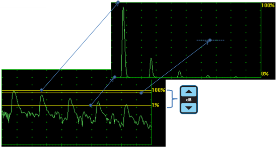
Thanks to keeping the receiver's linearity over 140 dB dynamic range the signals may be presented with the use of logarithmic scale; comparing to the linear scale signals presentation
the logarithmic scale presentation will not depend on the Gain setting, which defines just the position of 3 parallel lines above the logarithmic A-Scan:
the upper line corresponds to 100% level of the linear scale A-Scan
the lower line corresponds to 1% level of the linear scale A-Scan
the middle (red) line corresponds to 50% level of the linear scale A-Scan
In the Dual A-Scan mode the observation of the signals with use of the linear and logarithmic vertical scale is possible:
The instrument screen video below illustrates the versatility of the time domain signal presentation in ISONIC 3505
The receiver of ISONIC 3505 is equipped with 32-Taps FIR band pass with controllable lower and upper frequency limits. This allows improving of the signal to noise ratio for both traditional and
non-linear acoustics technique based inspections
Note: In order to accelerate the data stream the videos above are linked to the Youtube. In case the YouTube may not be accessed from your location please use the links below
ISONIC 3505 is equipped with 2 independent gates (A and B) for settling of the Region of Interest (ROI), alarming the defect events, and signals evaluation
The instrument carries the ability of Gain per Gate A and Gain per Gate B control over the entire gain manipulation range from ñ30 through +110 dB independently on the global instrument gain setting:
up to 3 independent gain settings may be acting within the same A-Scan. This opens the opportunity of observation and monitoring of the weak and strong signals simultaneously without any loss of data. The
Gain per Gate settings dominate over the Global Instrument Gain; in case of the full or partial matching of the Gate A and Gate B the Gain per Gate A setting has a priority
This functionality is very useful for the large number of inspections where the defects are detected through the receiving of echoes exceeding the certain threshold level and through back wall echo drop
(for example, the back echo attenuator based applications)
The instrument screen movie below illustrates controlling of the Gates A and B, the Alarm Logic, and Gain per Gate:
The Display Delay and Range of the A-Scan may be toggled from the currently applied settings to the Gate view and back as it is illustrated by the instrument screen movie below
For some inspection applications it may be very useful keeping some reference signal at the desired standard level whilst scanning OR bring the signal obtained from the certain region of interest defined by the Gate A
to the standard level. The example of using the normalized A-Scan allowing bringing of the signal from the discontinuity to the desired standard level is illustrated by the video below. The
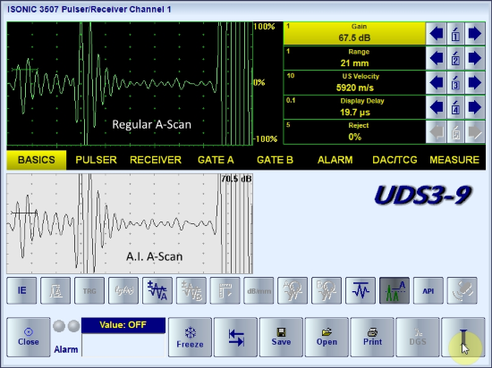
normalized A-Scan / Artificial Intelligence A-Scan is used at parallel with the regular:
Usually for the immersion inspection it is necessary to start A-Scan upon receiving the interface chow from the material surface ñ for that purpose the instrument is featured with the IE (interface echo) gate that should
be settled appropriately: the first signal crossing the IE gate level initiates the new A-Scan resettling the Display Delay accordingly following probe to material distance in real time. The process is
illustrated by the video below:
Note: In order to accelerate the data stream the videos above are linked to the Youtube. In case the YouTube may not be accessed from your location please use the links below
ISONIC 3505 is featured with 3 ways for creating DAC, TCG. Independently on the way the DAC was created there are provided:
up to 3 additional curves with the operator's selected dB-displacement in +/- 30 dB range
positioning of the main and additional DAC curves according to the Global Instrument Gain manipulated by an operator
one-click toggling between DAC and TCG
varying Display Mode whilst DAC or TCG is active
The instrument screen movie below illustrates the typical DAC/TCG manipulations on the series of back wall echoes whilst using ISONIC 3505:
Experimental DAC
The experimental DAC is created through recording as sequence of echoes from the equal reflectors detected through various sound paths; the maximal capacity 40 echoes (points). The user friendly dialogue
is combined with the Gain per Gate bringing each echo maximum in the Region of Interest defined by the gate position to the commonly used level of 80...90%% FSH automatically and
extremely easing maximizing of each indication taken into the DAC without affecting the Global Instrument Gain setting
The videos below illustrate the examples of preparing experimental DAC for the shear and longitudinal wave inspections with use of SDH (side drilled hole) and FHB (flat bottom hole) artificial reflectors correspondingly:
Theoretical DAC (dB/mm , dB/inch)
For some applications it may be required to create a DAC through entering of dB/mm (dB/inch) factor.
The goal of the calibration is to provide matching the tips of back wall echoes with the DAC line. To start the calibration it is necessary to obtain the A-Scan, on which the amplitude of the first
back wall echo doesnít exceed 100% FSH; along with keying in dB/mm (dB/inch) factor the DAC may be displaced in the vertical direction
The instrument screen movie illustrating dettling of dB/mm DAC is shown below:
The video showing the whole process is below:
DGS
The expandable database for the standard probes is carried by the instrument allowing using of the DGS technology for the sensitivity calibration and distance amplitude correction. The calibration
is performed in the user friendly dialogue as it is illustrated by the videos below
DGS calibration for 1.5 mm FBH sensitivity with MWB-45-4 probe
DGS calibration for 2 mm FBH sensitivity with MWB-60-2 probe
DGS calibration for 2.4 mm FBH sensitivity with SWB-60-5 probe
Note: In order to accelerate the data stream the videos above are linked to the Youtube. In case the YouTube may not be accessed from your location please use the links below
Signal Templates
Rapid and simple distinguishing of the signals characterizing evaluated properties of materials, internal discontinuities, etc may be achieved through pre-storing storing of corresponding waveforms template and displaying the live A-Scan
and the templates on the same screen - an example is illustrated by the video below:
Note: In order to accelerate the data stream the videos above is linked to the Youtube. In case the YouTube may not be accessed from your location please use the links below
Ultrasonic Spectroscopy - Frequency Domain
Materials Characterization and Sorting
Screening and Evaluation of HTHA Damages
Defects Pattern Analysis
Probes Characterization
Whilst implemented either in pulse-echo or pitch-catch mode the Ultrasonic Spectroscopy (uSpectroscopy) is based on the analysis of the frequency spectrum of the pulses passed through the material.
The frequency spectrum of the ultrasonic signals is measured and evaluated in addition to their time-of-flight and amplitude
uSpectroscopy may be implemented by digital ultrasonic flaw detector either phased array (PA) or conventional featured with the function of Fast Fourier Transform (FFT) converting the stream of
digital data representing the digitized ultrasonic signal (Time Domain) into the Spectrum data array reflecting the distribution of the signal energy by frequencies (Frequency Domain)
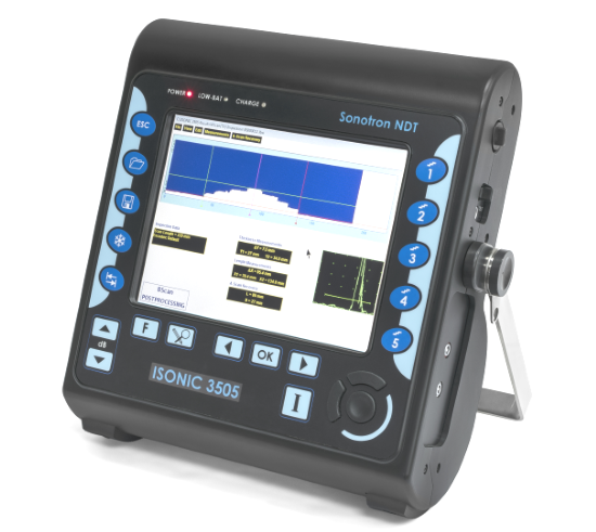
In the ISONIC 3505, ISONIC 3507 inbstruments the Frequency Domain signal presentation is available through the FFT display mode provided the DAC, DGS, TCG functions are inactive. The FFT graph
is accompanied with the it's source Time Domain RF A-Scan
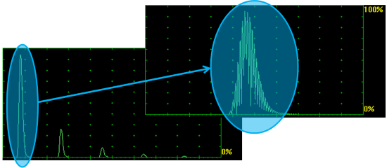
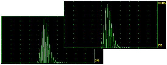
The FFT graph may be presented with the use of either linear or logarithmic vertical scale. The instrument screen movie below illustrates the frequency domain signal presentation and evaluation
Thanks to the 140 dB dynamic range of the never-saturated receiver of ISONIC 3505, ISONIC 3507 the Frequency Domain signal presentation doesn't depend on the instrument gain:
The Frequency Domain signal presentation is very useful for the probes characterization, express screening or determining of the material properties including microstructure, defect pattern analysis, other numerous purposes
An example of the quick probe characterization is provided in the video below:
The videos below show the use of FFT for the High Temperature Hydrogen Attack (HTHA) damages screening and evaluation according to the classic approach:
The videos below illustrate the use of FFT templates for materials probing, sorting, and characterization:
The FD B-Scan (Frequency Domain B-Scan) record and image may be formed out of the sequence of FFT data readings captured whilst scanning along the desired line on the surface of the material - refer to:
Note: In order to accelerate the data stream the videos above are linked to the Youtube. In case the YouTube may not be accessed from your location please use the links below
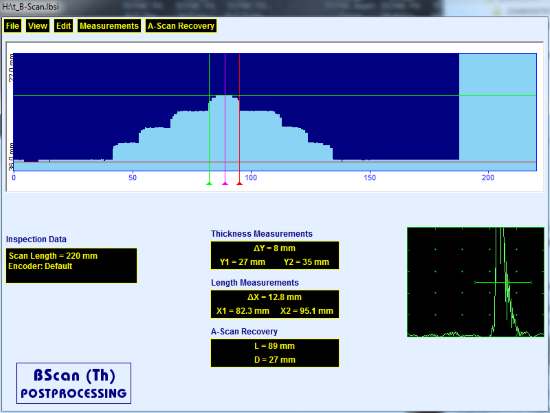
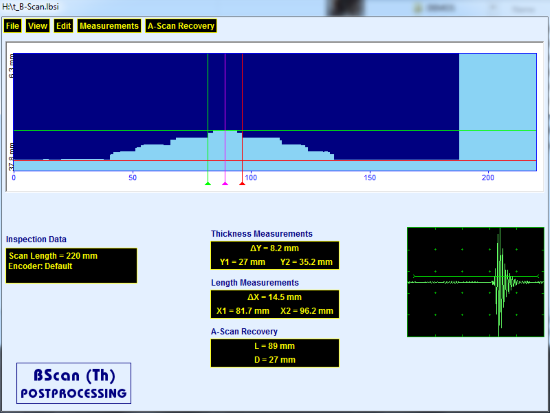
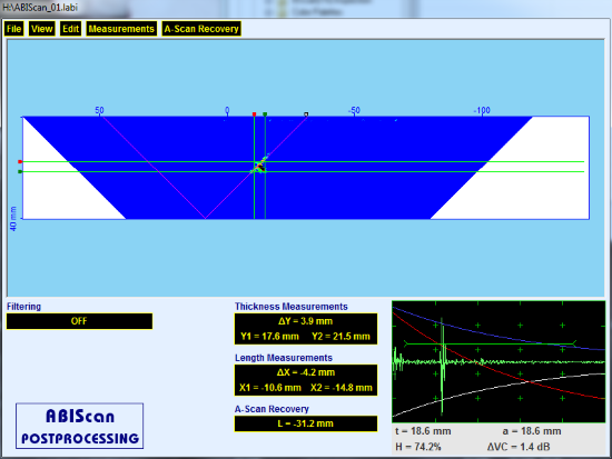
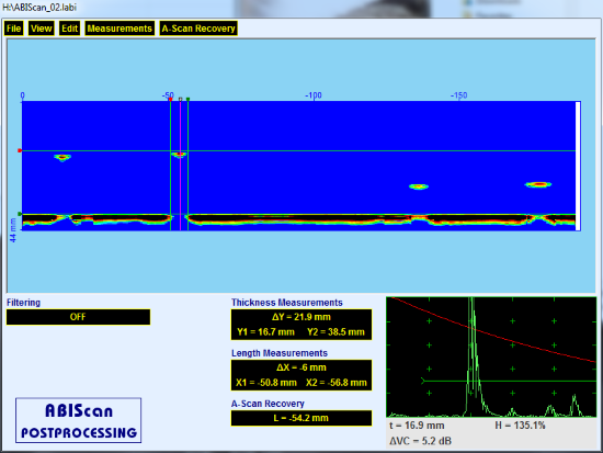
Thickness B-Scan
The Thickness Profile imaging and recording is performed through the continuous capturing of the thickness readings along the probe trace:
Both time-based (real time clock) and true-to-location (built-in incremental encoder interface) modes of data recording are supported
The complete sequence of A-Scans is recorded along with the thickness profile
Use of the water delay / rolling / immersion probes is supported thanks to the interface echo triggering feature
The off-line evaluation of the thickness profile record is featured with:
XY-sizing of the thickness damages:
Remaining thickness
Thickness loss
Length
Play-back and evaluation of the A-Scans captured during the scanning
Reconstruction of the thickness profile image for the various independently manipulated settings such as:
Global Gain
Gain per Gate A
Start / Width of the Gate A
Gain per Gate B
Start / Width of the Gate B
A-Scan Display (signal presentation either RF, full and half wave rectified)
Standard UT evaluation of the signals for every captured A-Scan
Conversion of the thickness profile B-Scan data into MS Excel® spreadsheet meeting the requirements of various Risk Based Inspection and Maintenance (RBIM) procedures
Thanks to the full dynamic range raw data capturing the stored Thickness B-Scan record may be processed off-line at every desired
global Gain / Gain per Gate A / Gate per Gate B between -30 and +110 dB
Typical Application: Corrosion characterization
Movie for the Thickness Profile data recording and imaging:
Examples of the Thickness B-Scan postprocessing screens:
The screen movie below illustrates the typical postprocessing functions for the Thickness B-Scan record:
Note: In order to accelerate the data stream the videos above are linked to the Youtube. In case the YouTube may not be accessed from your location please use the link below
DOWNLOAD AND PLAYBACK THE EXEMPLARY INSTRUMENTS FILES
The files should be extracted from the archive and played in the regular PC running under Win'XP, 7, 8, 10, 11 with use of the freely distributable
ISONIC OFFICE 35 software package
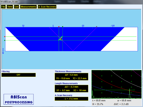
Flaw Detection B-Scan
The Flaw Detection B-Scan cross-sectional imaging and recording of defects for longitudinal and shear wave inspection is performed through the continuous measuring of the echo amplitudes and reflectors coordinates along the probe trace:
Both time-based (real time clock) and true-to-location (built-in incremental encoder interface) modes of data recording are supported
The B-Scan image is formed according to the incidence angle / skip
The complete sequence of A-Scans is recorded along with the B-Scan image
The editable echo-amplitude color palette allows reproducing of B-Scan image using the desired set of colors utilizing either linear or DAC/DGS normalized coding
Use of the water delay / rolling / immersion probes is supported thanks to the interface echo triggering feature
Off-line evaluation of the B-Scan record is featured with:
Sizing of the defects:
Coordinates
Projection dimensions
Maximal echo-amplitude
Play-back and evaluation of the A-Scans captured during the scanning
Defects outlining and the echo-dynamic pattern analysis
Reconstruction of the B-Scan image for the various independently manipulated settings such as:
Global Gain
Gain per Gate A
Start / Width of the Gate A
Gain per Gate B
Start / Width of the Gate B
A-Scan Display (signal presentation either RF, full and half wave rectified)
Distinguishing between half-skip / full skip detected defects (for the angle beam inspection)
Standard UT evaluation of the signals for every captured A-Scan
Thanks to the full dynamic range raw data capturing:
the stored B-Scan record may be processed off-line at every desired global Gain / Gain per Gate A / Gate per Gate B between -30 and +110 dB
DAC/DGS normalizing of the B-Scan image provides the same visualization for the variously settled instrument Gain
Typical Applications: Pulse echo inspection of welds, composites, metals, plastics, and the like
Movie for the 0-deg Flaw Detection B-Scan data recording and imaging:
Movies for the Angle Beam Flaw Detection B-Scan data recording and imaging:
Examples of the Angle Beam / Straight Beam B-Scan postprocessing screens:
Note: In order to accelerate the data stream the videos above are linked to the Youtube. In case the YouTube may not be accessed from your location please use the links below
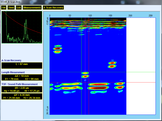
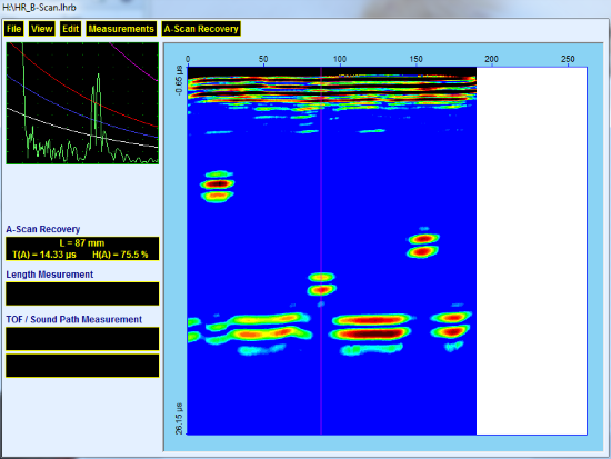
Straight Beam Flaw Detection High Resolution B-Scan (HR B-Scan)
Straight Beam Flaw Detection HR B-Scan cross-sectional imaging and recording of defects is performed through the continuous measuring of the echo amplitudes and reflectors coordinates along the probe trace:
Both time-based (real time clock) and true-to-location (built-in incremental encoder interface) modes of data recording are supported
The complete sequence of High Resolution A-Scans (HR A-Scans) is recorded along with the HR B-Scan image
The editable echo-amplitude color palette allows reproducing of HR B-Scan image using the desired set of colors utilizing either linear or DAC/DGS normalized coding
Use of the water delay / rolling / immersion probes is supported thanks to the interface echo triggering feature
Off-line evaluation of the HR B-Scan record is featured with:
Sizing of the defects:
Coordinates
Projection dimensions
Maximal echo-amplitude
Play-back and evaluation of the HR A-Scans captured during the scanning
Defects outlining and the echo-dynamic pattern analysis
Reconstruction of the HR B-Scan image for the various independently manipulated settings such as:
Global Gain
Gain per Gate A
Start / Width of the Gate A
Gain per Gate B
Start / Width of the Gate B
A-Scan Display (signal presentation either RF, full and half wave rectified)
Standard UT evaluation of the signals for every captured HR A-Scan
Thanks to the full dynamic range raw data capturing:
the stored HR B-Scan record may be processed off-line at every desired global Gain / Gain per Gate A / Gate per Gate B between -30 and +110 dB
DAC/DGS normalizing of the HR B-Scan image provides the same visualization for the variously settled instrument Gain
Typical Applications: Pulse echo inspection of composites, plastics, and the like
Movie for the Straight Beam HR B-Scan data recording and imaging on the special extremely attenuating high temperature resistant high strength carbon fiber (CF) sheet:
Movies for the Straight Beam HR B-Scan data recording and imaging on the GFRP material:
Examples of the HR B-Scan postprocessing screens:
The screen movie below illustrates the typical postprocessing functions for the HR B-Scan record:
Note: In order to accelerate the data stream the videos above are linked to the Youtube. In case the YouTube may not be accessed from your location please use the links below
DOWNLOAD AND PLAYBACK THE EXEMPLARY INSTRUMENTS FILES
The files should be extracted from the archive and played in the regular PC running under Win'XP, 7, 8, 10, 11 with use of the freely distributable
ISONIC OFFICE 35 software package
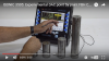
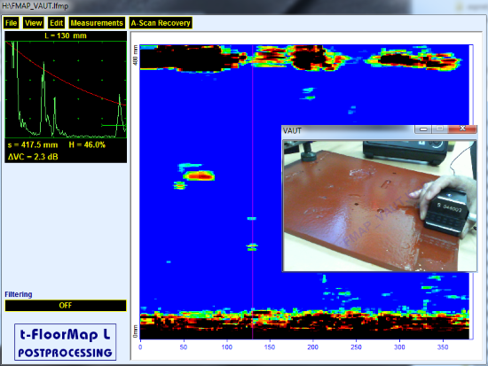
Flaw Detection / Screening CB-Scan
The Flaw Detection / Screening CB-Scan horizontal plane-view imaging and recording of the defects for shear, surface, and guided wave inspection is performed through the continuous measuring of the echo amplitudes and reflectors
coordinates along the probe trace:
Both time-based (real time clock) and true-to-location (built-in incremental encoder interface) modes of data recording are supported
The editable echo-amplitude color palette allows reproducing of HR B-Scan image using the desired set of colors utilizing either linear or DAC/DGS normalized coding
The complete sequence of A-Scans is recorded along with the CB-Scan image
Off-line evaluation of the CB-Scan record is featured with:
Sizing of the defects:
Coordinates
Projection dimensions
Maximal echo-amplitude
Play-back and evaluation of the A-Scans captured during the scanning
Defects outlining and the echo-dynamic pattern analysis
Reconstruction of the CB-Scan image for the various independently manipulated settings such as:
Global Gain
Gain per Gate A
Start / Width of the Gate A
Gain per Gate B
Start / Width of the Gate B
A-Scan Display (signal presentation either RF, full and half wave rectified)
Standard UT evaluation of the signals for every captured HR A-Scan
Thanks to the full dynamic range raw data capturing:
the stored CB-Scan record may be processed off-line at every desired global Gain / Gain per Gate A / Gate per Gate B / Gain per Gate A / Gate per Gate B between -30 and +110 dB
DAC/DGS normalizing of the CB-Scan image provides the same visualization for the variously settled instrument Gain
Typical Applications: SRUT GW and CHIME inspection of the annular rings, plates, pipewalls, shells, and the like for the pitting, stress corrosion, etc; weld inspection, surface wave inspection
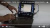
Movies for the CB-Scan horizontal plane-view imaging principle - Short Range Guided Wave Inspection (SRUT GW) of the Plates:
Movie for the CB-Scan horizontal plane-view imaging principle - Short Range Guided Wave Inspection (SRUT GW) of the Pipe Wall - Circumferential Insonification:
Movie for the CB-Scan horizontal plane-view imaging principle - Short Range Guided Wave Inspection (SRUT GW) of the Pipe Wall - longitudinal Insonification:
Movie for the CB-Scan horizontal plane-view imaging principle - Short Range Guided Wave Inspection (SRUT GW) of Annular Ring plates in the above ground storage tanks:
Movie for the CB-Scan horizontal plane-view imaging principle - Short Range Guided Wave Inspection (SRUT GW) of Annular Ring plates in the above ground storage tanks - use of the DAC Normalized Mapping providing
compensation of the liquid influence to the scanning results:
Examples of the CB-Scan postprocessing screens for the SRUT GW inspection:
The screen movies below illustrate the typical postprocessing functions for the SRUT GW CB-Scan record (in the present example the scanning process was recorded by the instrument along with the CB-Scan map
using VAUT):
Note: In order to accelerate the data stream the video above is linked to the Youtube. In case the YouTube may not be accessed from your location please use the link below
DOWNLOAD AND PLAYBACK THE EXEMPLARY INSTRUMENTS FILES
The files should be extracted from the archive and played in the regular PC running under Win'XP, 7, 8, 10, 11 with use of the freely distributable
ISONIC OFFICE 35 software package
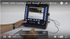
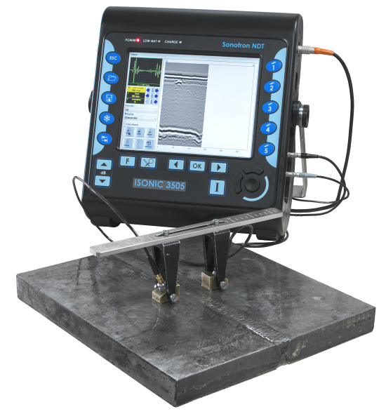
TOFD / CHIME / RF B-Scan
TOFD / CHIME Inspection is performed through continuous record of of RF A-Scans obtained through passing of ultrasonic wave through the material between two angle beam longitudinal wave probes:
Both time-based (real time clock) and true-to-location (built-in incremental encoder interface) modes of data recording are supported
The complete sequence of RF A-Scans is recorded along with the TOFD / CHIME map
Whist scanning as per operator's selection:
all A-Scans may be normalized based in real time so the reference signal (for example - lateral wave) will have the same amplitude within entire record (TOFD / CHIME Record Stabilizer)
Averaging the recorded A-Scans may be performed
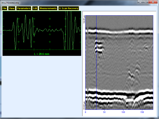
Off-line evaluation of the TOFD Map - the all-functional TOFD postrpocessing is featured with:
Improvement of the near surface resolution through the removal of lateral wave and/or back echo record
Linearization and straightening
Normalizing of the recorded A-Scans through bringing the selected reference signal (for example - lateral wave) to the desired standard level within entire record
Play-back and evaluation of the A-Scans obtained during the scanning
Reconstruction of the TOFD Map for the various independently manipulated settings such as:
Global Gain
Gain per Gate A
Start / Width of the Gate A
Gain per Gate B
Start / Width of the Gate B
Manipulating the contrast of the TOFD image through varying ADC grades and/or rectification
Defects pattern analysis and sizing:
Depth
Height
Position along the fusion line and Length: parabolic cursors and SAFT are applicable
Zoom of TOFD Map and A-Scans
Standard UT evaluation of the signals for every captured A-Scan
Thanks to the full dynamic range raw data capturing the stored TOFD / CHIME / RF B-Scan record may be processed off-line at
every desired global Gain / Gain per Gate A / Gate per Gate B between -30 and +110 dB
Typical Applications: TOFD modality weld inspection; CHIME inspection; Inspection of composites based on RF B-Scan recording
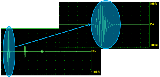
Exemplary video below illustrates TOFD A-Scan for the sharp edged planar vertical and compact discontinuities:
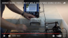
Movies for the TOFD Recording and Imaging (with and without mode conversion back echo recording / scanning performed with use of the encoder and scanner):
Typical TOFD record for the weld inspection:
TOFD / CHIME Record Stabilizer
The typical way for settling of the instrument Gain prior to the TOFD inspection is bringing the amplitude of lateral wave signal to the desired standard level, usually - between 30 and 60% of the FSH
(Full Screen Height). Whilst scanning the amplitude of the lateral wave signal may fluctuate due to various reasons such as coupling deviations, inhomogeneity of the weld structure, and the like.
Such fluctuations affect the quality of TOFD record
As ISONIC 3505 carries exceptionally innovative ultrasonic card with never-saturated-receiver, which keeps the linearity over 140 dB dynamic range digitizing the originally received signals
independently on the gain and rectification settings in every firing / receiving cycle. This unique feature allows generating of the so called Artificial Intellect (A.I.) A-Scan along with the regular one simultaneously
The A.I. A-Scan is based on the digitizing signal over 140 dB dynamic range (real time 32-bits A/D conversion). For the data digitized in such manner the Gain setting defines not the sensitivity but the scaling factor
applied to the FSH. The A.I. A-Scan allows gating of the signal, for example - lateral wave (or part of it) and real time scaling bringing the highest amplitude within entire Gate to the predefined standard level, for example 60%
Whilst scanning the highest half-wave of the lateral wave signal has been kept at the standard level permanently - this provides the stability and consistency of the TOFD record for the varying coupling conditions
and other factors influencing the quality of the recorded signals as it is illustrated by the instrument screen video below:
Note: In order to accelerate the data stream the videos above are linked to the Youtube. In case the YouTube may not be accessed from your location please use the links below
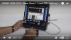
Multi A-Scan and Strip Chart
ISONIC 3505 allows obtaining of several (up to 4) A-Scans out of the same probe (pair of probes) simultaneously in every emitting / receiving cycle. For each A-Scan the following parameters may be settled independently on others:
Timebase: Display Delay and Range
Gain
Signal presentation either RF or rectified
Gates start, width and threshold
Signal evaluation readout
Strip chart may be formed out of the said A-Scans and recorded along the scanning line: each A-Scan represents corresponding section (Region of Interest - ROI) of the material
Note: In order to accelerate the data stream the video above is linked to the Youtube. In case the YouTube may not be accessed from your location please use the links below
uSpectroscopy - Frequency Domain B-Scan (FD B-Scan)
The FD B-Scan (Frequency Domain B-Scan) record and image are formed out of the sequence of FFT data readings captured whilst scanning along the desired line on the surface of the material. This allows
quick and precise distinguishing and sizing of the areas with different microstructure / mechanical properties
Note: In order to accelerate the data stream the videos above are linked to the Youtube. In case the YouTube may not be accessed from your location please use the links below
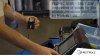
C-Scan - Raster Scanning
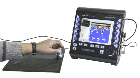
Manual Raster Scanning remains to be the optimal solution for the numerous inspection tasks such as ultrasonic testing of relatively small composite parts, detection of impact damages under the flying
surfaces of aircraft, corrosion mapping, and the like where the mechanic-free probe positioning is desired by most of users
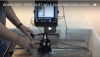
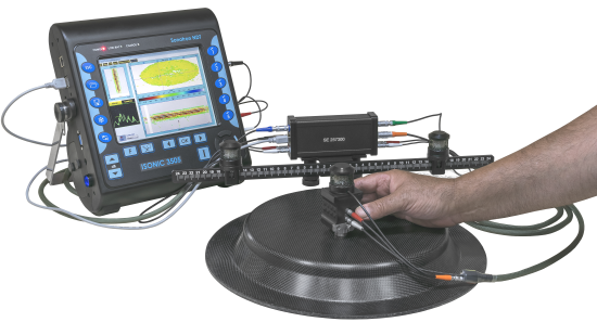
The airborne ultrasound based encoder powered and communicating with the instrument through USB port monitors the probe position and swiveling angle for the conventional / PA probes manipulated over the
flat or curved surfaces. The main module of the encoder carries the electronic box and the bar with airborne ultrasound receivers. Prior to the scanning it is placed onto the part under test or at some proximity
to it by means of either magnetic legs or vacuum cups. The encoder is connected to the ISONIC 3505 instrument via USB cable and the light thin umbilical extending the probe connection terminals. Another light
thin umbilical connects the probe used for the inspection to the corresponding extended terminal(s) and the airborne ultrasound emitter situated on the top of the probe to the electronic box. Single element airborne
ultrasound emitter is sufficient for the XY-positioning of the probe; dual emitter is required for the XYþ-positioning where þ is the probe swiveling angle
The probe coordinates on the material and swiveling angle are monitored continuously and transmitted to the inspection software providing capturing of the corresponding A-Scans (conventional modality) and A-Scan sets (PA modality)
for every encoded position along the scanning trace. The inspection software packages for the ISONIC 3505, ISONIC 3507, and ISONIC 3510 instruments allow:
Compression wave flaw detection and thickness (corrosion) mapping of the parts with flat and curved surfaces with use of single or twin element conventional probes and linear array / dual linear PA probes
Short Range Guided Wave (SRUT) inspection of annular rings, pipe walls, tank shells, and the like with use of mono-element SRUT probes and wedged PA probes
Weld inspection with use of PA probes etc
The B-, C-, CB-Scan and 3D data presentation are provided
The exemplary movies for the airborne ultrasound encoded mechanics-free raster scanning and recording:
1. Instruction video on connection of airborne ultrasound encoder to the instrument and to the receivers followed by the calibration for the actual values of airborne ultrasound velocity and sensors delays
2. Instruction video on the XY scanning with 0-degree probes
3. Instruction videos on the XYþ scanning with the use of short range guided wave (SRUT GW), angle beam shear wave, surface wave probes
3.1. For the placement of airborne ultrasound receivers in front of the probe
3.2. For the placement of airborne ultrasound receivers behind the probe
4. Screening and mapping of the corrosion damages below the soil level in the steel poles legs (air-to-soil interface)
5. Corrosion (thickness) mapping using 0-degree probe
6. Flaw detection and mapping of composite panels
7. SRUT GW inspection
Use of the water delay / rolling / immersion probes is supported thanks to the interface echo triggering feature
Performing of the automatic XY-scanning in contact / immersion modes is also possible when using optional dual axis encoder interface, which connect the scanner's encoders to the instrument's USB port
Note: In order to accelerate the data stream the videos above are linked to the Youtube. In case the YouTube may not be accessed from your location please use the links below
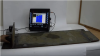
IUT ñ Immersion Ultrasonic Testing
ISONIC 3505 featured with the interface echo function and carrying powerful on-board computer is suitable for the rapid high resolution immersion ultrasonic testing (IUT); the automatic
scanning mechanism is controlled through USB port. The use of an external PC is not a must
An example of the IUT routine including the quick preparing for the inspection, scanning with 100% raw data capturing, and postprocessing is illustrated by the video below
Note: In order to accelerate the data stream the video above is linked to the Youtube. In case the YouTube may not be accessed from your location please use the links below
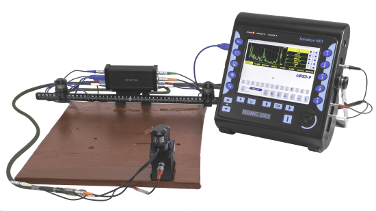
ISONIC 3505 LF
ISONIC 3505 LF is the modified version of ISONIC 3505 adopted for the low frequency ultrasound applications. It is characterized by the appropriately modified frequency band of the receiver and the limits for manipulating duration of
the initial pulse ñ refer to Technical Data
ISONIC 3505 LF is suitable for the inspection of highly attenuating materials such as concrete, fiberglass, rubber, special purposes composites and other materials, etc. The upper limit of the frequency band keeps the opportunity for the
inspection of metals and the like
The videos below illustrate A-Scan based evaluation of concrete
In the terms of data recording and imaging, remote control, and the like the functionality of ISONIC 3505 LF remains to be the same as in the ISONIC 3505
Note: In order to accelerate the data stream the videos above are linked to the Youtube. In case the YouTube may not be accessed from your location please use the links below
UT over IP - Remote Control and Data Acquisition
Thanks to the Client ñ Server software architecture ISONIC 3505 may be controlled remotely from a regular PC running under WiníXP, 7, 8, 10, 11. There is no need in the special software for that purpose,
just download and install in the PC the same software as used in the instrument
The software installed in the PC should be of the same release as the software running in the ISONIC 3505 and correspond to the instrument model
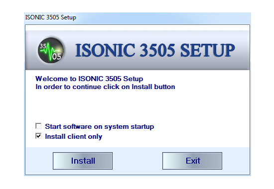
Installing the Instrument Software in the PC
Upon started the installation routine generates the dialogue as below on the PC screen:
It is necessary to check Install client only and uncheck Run on windows startup option then to click on Install button. Further actions are taken by the installation routine automatically
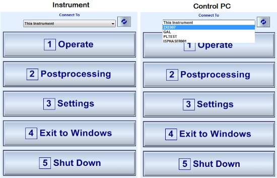
Controlling the Instrument from the PC
The instrument and the computer should be connected to the same LAN or Wi-Fi and obtain the IPs automatically. The initial Startup menu (Start Screen) appearing upon powering the instrument on and booting up completed
should be kept on the unit's screen at the time of establishing the remote connection and control. In the computer the same software should be launched: on appearing of the Startup menu it is necessary to select the instrument
to be controlled from the list of the available Idle units:
Once the connection is established ISONIC 3505 unit enters into the slave mode being connected to the probes and encoder and running the just the server routine while the computer performs full control of the instrument,
data acquisition, processing, and storage on the local drives through running of the client software in the same manner as the instrument does when operating autonomously
The video below illustrates the UT over IP feature:
Extremely simply and quickly implementable UT over IP mode of operation is the standard feature of all ISONIC series portable instruments, namely
For all above listed units the remote control and data acquistion are realized in the same manner as it is shown in the present video
Note: In order to accelerate the data stream the video above is linked to the Youtube. In case the YouTube may not be accessed from your location please use the links below


 UDS 3-9 Pulser Reciever provides the top level A-Scan ultrasonic flaw detector functionality of ISONIC 3505. In the instrument it is used for the various pure A-Scan based inspections and
for calibration purposes prior to the inspections performed with the data recording through either Line- or Raster- scanning
UDS 3-9 Pulser Reciever provides the top level A-Scan ultrasonic flaw detector functionality of ISONIC 3505. In the instrument it is used for the various pure A-Scan based inspections and
for calibration purposes prior to the inspections performed with the data recording through either Line- or Raster- scanning