

|

|

|

|

|

|

|

|

|

|

|

|

|

|

|

|

|

|

|

|

|

|

|

|

|

|

|

|

|

|
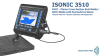
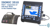
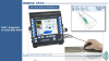
PA UT (PAUT): Planar and Circumferential Butt Welds, Rails, etc


|

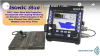
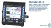
This inspection software option is available for the ISONIC 3510T / ISONIC 3510, ISONIC 2010, and ISONIC 2009 UPA Scope instruments and featured with:
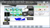
- True-To-Geometry Weld Overlay Volume Corrected Imaging - Cross Sectional and Top (C-Scan)- / Side- / End- View and 3D
- Sector-Scan Cross Sectional Coverage
- Intuitive Image Guided PA Pulser Receiver with Beam Forming View
- DAC / TCG Normalization
- Built-In Weld Geometry Editor and Ray Tracer - Scanning Pattern Design
- Automatic Curvature Correction for the wedges with contoured contact face (FILLET CU)
- Independent on TCG Angle Gain Compensation / Gain Per Focal Law Correction
- Automatic Coupling Monitor
- Automatic Scanning Integrity Monitor
- Detection of the defects in the parent material simultaneously with weld inspection
- Encoded and Time based C-Scan
- 100% Raw Data Capturing
- FMC/TFM Protocol for the data acquisition and imaging
- Automatic Defects Alarming Upon C-Scan Acquisition Completed
- Automatic Creation of Editable Defects List
- Automatic Creating of Scanning Integrity Report Upon C-Scan Acquisition Completed
- Comprehensive Postrpocessing Toolkit Including:
- Recovery and Evaluation of Captured A-Scans from the Recorded Cross Sectional Views (Sector Scan) and C-Scans
- Recovery of the Cross Sectional Views from the Recorded C-Scan data
- Converting Recorded C-Scans or their Segments into 3D Images
- Off-Line Gain Manipulation
- Off-Line DAC to TCG / TCG to DAC toggling for all types of stored files (A-Scans, cross-sectional views, C-Scans, etc)
- Off-Line DAC Normalization of the Recorded Images / DAC Evaluation
- Off-Line editing of Angle Gain Compensation / Gain per Shot Correction applied to the stored the Cross-sectional Views / C-Scan data
- Numerous Filtering / Reject Options ( by Geometry / Position / By Amplitude db-toDAC / etc ) and Regeneration of the Corresponding of Editable Defects List and Storing it into a Separate File
- Defects Sizing
- Automatic Creation of Defect List and Storing it Into a Separate File
- Automatic Creating of Scanning Integrity Report
- Automatic creating of inspection reports - hard copy / PDF File
The tutorial videos for ISONIC EXPERT are present below:
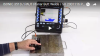
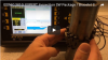
The movie below illustrates inspection of planar butt welds with coupling monitoring and checking for the laminations in the heat affected zone. ISONIC 3510 instrument and draw wire encoder are used
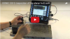
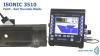
The movies below illustrate inspection of planar and circumferential butt welds with use of the ISONIC 3510T / ISONIC 3510 instrument whilst the encoding of probe position is performed either by the magnetic wheel or draw wire encoder
The movie below presents the rope / scaffolding access inspection of circumferential butt weld with the use of chain scanner. The VAUT technology is involved to provide the video weld tracking record embedded into PA UT data file
The videos below show the detection of longitudinal cracks in the crown and in the bottom bead of the thin wall stainless steel welds
The movie below illustrates the use of ISONIC 2010 instrument and the bracelet scanner whilst scanning the reference block for the inspection of circumferential butt welds in the small OD boiler tubes
Another task resolved with the use of ISONIC EXPERT software application is the inspection of the rail thermite welds:
The one-click-implemented automatic generation of the editable defects list is featured with:
- Position along the fusion line and length
- Depth and projection height
- Position in the cross-section and the projection width
- Area size
- Maximal and average echo amplitudes (dB-to-DAC / dB-to-Gate-level)
- True-to-geometry 3D-imaging of each defect highlighted at the background of weld volume and other defects nearby extremely easing and speeding up data interpretation thanks to the provided ability of 3D-view manipulation
As per operator's will the defects list may be generated by the instrument for every weld section immediately upon the scanning completed. Alternatively the defects list may be created at the postprocessing stage any moment upon the scanning file is open either in the instrument or in the regular PC running under Win'XP, 7, 8, 10, 11 with use of the freely distributable ISONIC PA Office software package as it is illustrated in the exemplary video below representing the defects characterization and interpretation for a test piece of austenitic weld comprising large number of discontinuities. But even for the weld, which is really full of various defects, the highest rapidness of the data interpretation is provided:
The movie below illustrates the results of scanning of the Z-Cut ASTM E-1961 calibration block for the inspection of girth welds; the block contains reference reflectors (flat bottom holes and notches) at various locations. The pure S-Scan, the EquPAS S-Scan coverage and imaging were aplied along with the TFM sharpening of the pure S-Scan data:
Note: In order to accelerate the data stream the videos above are linked to the Youtube. In case the YouTube may not be accessed from your location please use the link below
|
|
|

|
|

|
|
|

|

|
|
|
|
|
|
|
|
DOWNLOAD AND PLAYBACK THE EXEMPLARY INSTRUMENTS FILES
|
