
|

|
 | New Way for Utilizing DGS Technology M.Berke, W.-D.Kleinert, J.Reinersmann, U.Schlengerman, K.Volkmann, Krautkramer - Germany. M.Kritsky, A.Passi, G.Passi, Sonotron NDT - Israel |
- experimentally measured variations of amplitude with distance from flat bottom holes are known as DAC
- the standard universal attachment scales supplied with different kinds of Krautkramer high repeatable probes are known as DGS scales.
- selection of the value of Equivalent Diameter (disk shaped reflector) from appropriate box to characterize inspection sensitivity
- keying in the value of Material Attenuation characterizing object under test
- keying in the value of Transfer Loss characterizing coupling conditions
- maximizing the echo and fixing the probe in found position
- "tuning" diameter of flat bottom hole. This causes modifying of the DGS curve on the screen until peak of the echo received will reach the DGS curve level
- direct reading the value of equivalent diameter
The echo amplitude is main criteria for rejecting defected parts since the first practical use of ultrasonic echo technique.The DGS (AVG) diagrams announced by J.Krautkramer in were the first ones that used a disk-shaped reflector as a clear sensitivity and sizing reference, which was adopted immediately worldwide. Since then:
The major advantage of DGS scales is that they allow the calibration of sensitivity and the sizing of defects using one easy detectable reflector only (inner surface of the cylinder in the very reproducible reference standard). However, the disadvantage of known DGS is the relative complexity of the "spider's web" of universal attachment scale. The "one curve only" shape of experimental DAC makes it a preferred solution in many cases, in spite of the need to use numerous reference standards and blocks for each kind of probe, material and inspection task.
The new implementation of sensitivity calibration and defect sizing using DGS realized as image guided technology in USLTPR software for operating Krautkramer
The
 |  |
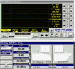
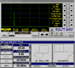
Initially operator selects probe from corresponding box: the corresponding variation curve for back echo amplitude with distance appears on the A-Scan simultaneously with the scheme of probe placement on the reference standard. The operator types the value of attenuation in the reference block selected automatically by the software. The keyed-in value of Reference Attenuation finalizes the shape of the Back Echo curve.
The next steps are:
At the last stage of DGS setup, the peak of the echo received by the probe placed on the reference standard must be adjusted to the back echo level. This is achieved through adjustment of the Gain value.
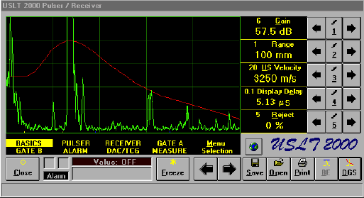
Upon completing the operator clicks on appropriate button causing the creation of DGS curve (red) on the A-Scan. The appearance of the DGS curve is accompanied by corresponding automatic Gain re-adjustment (in accordance with keyed in values of Equivalent Diameter, Material Attenuation, Transfer Loss and with types of probe and reference standard used).
In this way, the easily extendable DGS database for most Krautkramer probes is used without complicating operator's readings.

The back task is resolved while sizing the defect in three steps:
Both procedures significantly reduce the human uncertainty and time consumption while utilizing DGS making it easily understandable for any operator in the field and negating above mentioned "one curve only" DAC advantage.