

|

|
 | High Reliability Manual Ultrasonic Inspection G. Passi, M. Kritsky - SONOTRON. Y. Shoef - GABI SHOEF LTD. ISRAEL |  |
Abstract
- Because the reliability of low-cost conventional manual ultrasonic testing is limited by human factors, it couldn't compete with radiographic inspection in spite of the higher attainable flaw sensitivity. ISONIC - a new portable mechanics free PC assisted multitechnology ultrasonic inspection system is, for the first time, closing a gap allowing to perform ultrasonic testing with high reliability and objective data presentation.
Table of Contents
- Introduction
1. ISONIC - Components and Functioning
1.1. Preparing for making Inspection
1.2. Scanning - Searching for Defects
1.3. Interpreting and Documenting of Inspection Results
2. ISONIC - Innovating of Technical Solutions
2.1. Monitoring of Acoustic Coupling
2.2. Ultrasonic Probe Location and Swiveling Angle Monitoring
2.3. Echoes Processing and Flaws Imaging
2.4. Multitechnology
2.5. User Interface
3. ISONIC - when does it make profit
Conclusion
References
INTRODUCTION
- Ultrasonic testing with manual probe manipulation is in wide spread use because in most cases the automation of scanning procedure is not reasonable. For example, it's well known, that manual ultrasonic testing of welded joints is much cheaper than automated inspection when the length of the weld is not exceeding some threshold, which is about 1.5 to 10 m depending on the type of object under test, while 70% of total quantity are the welds shorter than 1 m [1,2]. Basing on many years experience of Gabi Shoef Ltd. - the large Israeli NDT service company operating worldwide, authors have concluded that the said threshold value is even higher on practice, because of the following:
- ordering for inspection of long welds is relatively not regular
- projects spans are extremely compressed
- inspection sites have variable geography and different working environments
- there are projects running simultaneously
- competition between NDT service companies limits the prices
- inspection results are totally dependent on the operator's skills, his actual performance of the testing in the field, his observation of the indications, and his own on the spot interpretation
- inspection report with "no indications found" sentence or consisting of list of the indications and, in best case, additional A-scan screenshots is non obvious as for welding personnel as for the end user
As a result, it often happens that manual ultrasonic inspection is more applicable even for the long welds.
It means that in the lot of cases the low-cost, safe and high sensitive conventional manual ultrasonic inspection is still an only alternative for radiography and there is no serious competition between two technologies because of the following deficiencies of ultrasonic inspection:
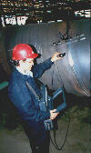 Fig 1. ISONIC - the new portable mechanics free PC assisted multitechnology ultrasonic inspection system |
1. ISONIC - COMPONENTS AND FUNCTIONING
- ISONIC is based on PC KONTRON IP Lite rugged industrial host computer (or regular DeskTop PC), equipped by Sonotron's original electronics and software operating under Windows'95. However, the regular desk top PC can be used as a host computer for in door applications. ISONIC also includes a set of Sonotron's original sensors, providing mechanics free monitoring of ultrasonic probe location and orientation (swiveling angle) on flat and curved surfaces, as well as monitoring of acoustic coupling between ultrasonic probe and the object under test.
- Skip #
- Scan Index
- Weld Thick
- Weld Width
- Base (for illustrated application the value of Base is determined by ISONIC automatically with respect to the values of Skip #, Weld Thick, Weld Width and Angle of ultrasonic probe; this value is to be observed by operator and confirmed before dynamic setup and starting of scanning)
- Weld Diameter
- Weld Length (the maximal available value for this parameter is determined by ISONIC automatically with respect to Weld Diameter)
- zero adjustment for probe location monitor with respect to the weld axis: button {Probe Location Monitor...} - for each new weld to be inspected
- calibration of acoustic coupling monitor: button {Coupling Monitor...} - for
- each new weld to be inspected
- checking and recalibration, if required, for current value of airborne ultrasound velocity: button {Airborne US Velocity...} in cases of more then 10o C temperature changes during one session
- reference images of two scanning traces required to be observed from both sides of the weld in order to provide 100% testing integrity (Scanning Pattern)
- current location of ultrasonic probe on the object under test - the cursor on ISONIC screen is true-to-scale following the ultrasonic probe manipulated by operator hand
- current degree of acoustic coupling - special label on the on the ISONIC screen and, as per operator's choice, the sound alarm of critical deviations of acoustic coupling
- incorrect ultrasonic probe swiveling angle - this will be indicated by change of following cursor shape on the ISONIC screen and showing of corresponding message
- probe positioning out of scanning area - this will be indicated by change of following cursor shape on the ISONIC screen and showing of corresponding message
- actual scanning trace realized by operator with sufficient acoustic coupling and correct swiveling angle - the image of probe trace will be interrupted in cases of insufficient acoustic coupling or incorrect swiveling angle of ultrasonic probe or when the scanning speed is too high. The limit for the scanning speed is determined by ISONIC automatically by measuring pulse repetition frequency of auxiliary ultrasonic flaw detector
- background imaging of Top View and Side View of inspected volume - unfolded shapes
- background imaging of Real Side View Shape of inspected volume
- projection images of flaws on background Top and Side Views with color coding of echoes amplitudes; images corrected with respect to current degree of acoustic coupling and ultrasonic probe swiveling angle superimposing of flaws projections detected from both sides of the weld and from different directions with storing maximal values of echoes amplitudes
After completing the scanning operator creates file with inspection results containing:
- graphics (Scanning Pattern, Top View, Side View)
- static and dynamic ISONIC parameters
- ultrasonic flaw detector name and its calibration dump
- ultrasonic probe name and parameters
- textual data about the object under test and inspection procedure
- amplitude filtering of flaw images - suppressing all indications below some threshold level as per user's choice
- measuring of three coordinates and three projection sizes for each flaw (in the directions along the weld, across the weld and in depth direction)
- zooming of flaw images
- automatic searching of maximal echo amplitude in the region of interest with further suppression all indications less the level - 6 dB of maximum found
- analyzing of flaw images using DGS or other scales (option)
ISONIC operates together with auxiliary standard ultrasonic flaw detector, for example, USK-7D, USN-50, USN-52, and standard ultrasonic probes, for example MWB, SWB, MSEB of Krautkramer. Other types of auxiliary ultrasonic flaw detectors and probes available, as well as ultrasonic flaw detector PC card inside the host computer (Figure 2). ISONIC recognizes external ultrasonic flaw detector automatically via RS232 cable and uses output of its amplifier as a source of analogue echoes.
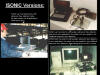 Fig 2. ISONIC - different realizations: Fig 2. ISONIC - different realizations:(a) Stand Alone System with ultrasonic flaw detector PC Card Inside - the optimal solution for all applications. Host Computer - KONTRON IP Lite (b) Add One System operating with the satndard auxiliarty ultrasonic flaw detector. Host Computer - KONTRON IP Lite (c) Add One System operating with the satndard auxiliarty ultrasonic flaw detector. Host Computer - regular desk top PC |
ISONIC is formalizing the ultrasonic testing procedures at all stages, allowing to avoid or, at least, to detect and to correct operator's errors easily. Such philosophy for operating of new generation ultrasonic equipment was created being based on numerous research works (see, for example, [3-5]).
1.1. PREPARING FOR MAKING INSPECTION
 Fig 3. Keying in the data about the object under test: 12 standard issues and textual free style comments Fig 3. Keying in the data about the object under test: 12 standard issues and textual free style comments Fig 4. Keying in the data about the testing procedure: 6 standard issues and textual free style comments Fig 4. Keying in the data about the testing procedure: 6 standard issues and textual free style comments Fig 5. . Keying in the name and parameters of ultrasonic probe Fig 5. . Keying in the name and parameters of ultrasonic probe Fig 6. Loading of calibration dump of auxiliary ultrasonic instrument via RS232 Fig 6. Loading of calibration dump of auxiliary ultrasonic instrument via RS232 Fig 7. A desk top for calibration of ultrasonic flaw detector PC card inside the ISONIC Fig 7. A desk top for calibration of ultrasonic flaw detector PC card inside the ISONIC Fig 8. An example of ISONIC desktop for setting up the static parameters and calling dynamic setup procedures with further starting inspection Fig 8. An example of ISONIC desktop for setting up the static parameters and calling dynamic setup procedures with further starting inspection |
The next step - keying in of ultrasonic probe name and parameters X-value, Angle and Zero, which are required for ISONIC data processing and documenting (Figure 5); then ISONIC recognizes auxiliary ultrasonic flaw detector and loads its calibration dump via RS232 (Figure 6) or allows to calibrate ultrasonic flaw detector PC card inside the host computer (Figure 7). The conventional ways are used to define parameters of ultrasonic probe and to calibrate auxiliary ultrasonic instrument, and the results can be rechecked and loaded into ISONIC in advance. This is extremely reducing the possibility of calibration mistakes, which are not so seldom: it is known, for example, that typical deviation for Gain calibrating is 2 to 3 dB, but, from time to time, the mistakes of up to 13 dB are possible [3].
The last step of preparing for making inspection is keying in the dimensions of object under test and scanning parameters with further ultrasonic probe location and swiveling angle monitor adjustment. The geometry of object under is to be taken into account now. As an example, the ISONIC application for inspection of circumferential butt weld is described here (Figure 8). ISONIC shows to the operator the placement of sensors on the object under test and requires for setting and/or confirming of 8 static parameters:
As for previous preparation steps as for the last one the data stored from previous ISONIC session is default. It does mean that operator has just to check settings from time to time when inspecting identical or similar objects.
After the settings of static parameters are observed and/or confirmed operator has to perform dynamic setup - the last procedure before scanning the object. The following issues have to be fulfilled:
All procedures of dynamic setup are extremely simplified and their results are documented as well as static parameters.
It is to be noted that there is no need in marking the region of probe manipulation on the surface of object under test, because ISONIC is automatically providing such marking in virtual space when starting scanning by pressing {Start Inspection...} button.
1.2. SCANNING - SEARCHING FOR DEFECTS
 Fig 9. ISONIC real time screen when inspecting a circumferential weld Fig 9. ISONIC real time screen when inspecting a circumferential weld |
The above 6 issues are completely indicating the testing integrity with simultaneous assistance to the operator just to perform scanning properly without thinking about echoes analysis. The echoes analysis is performed by ISONIC in completely automatic mode and provides (see again Figure 9):
1.3. INTERPRETING AND DOCUMENTING OF INSPECTION RESULTS
 Fig 10. a Fig 10. a
|
All the postprocessing results can be printed as attachments to inspection report (Fig 11. Example of ISONIC Postrocessing Page).
2. ISONIC - INNOVATING OF TECHNICAL SOLUTIONS
- Few examples below will illustrate ISONIC's innovating in technical solutions.
- ISONIC electronics includes two initial pulse generators for airborne ultrasound emitters and three amplifiers for airborne ultrasound receivers
- ultrasonic probe is mounted into the light weight probe holder which is equipped by double or single easy removable airborne ultrasonic emitter (as per operator's choice, Figure 13). The single airborne ultrasonic emitter allows to monitor coordinates of ultrasonic probe only; the double airborne ultrasonic emitter allows to monitor coordinates and swiveling angle of ultrasonic probe simultaneously
- in most cases (flat surfaces or curved surfaces with simple geometry, for example, pipes) two small undirected airborne ultrasound receivers and two amplifiers are employed for monitoring ultrasonic probe location and swiveling angle; the receivers are placed on the light weight ruler at known distance to one another
- if the geometry of scanning surface is more complicate the third small airborne ultrasound receiver and amplifier are employed
- low level processing is performed by original microchip providing gating, counting and measuring of echoes, as well as transferring to the main software current dumps of echoes data with respect to ultrasonic probe position and swiveling angle and the degree of acoustic coupling
- high level processing including imaging procedures is performed in the host computer. For the first time, the indefinity accompanying any echo pulse is taking in account. When receiving an echo the exact position of the reflector is unknown because of non zero width of ultrasonic beam. When making conventional inspection the operator always optimizes ultrasonic probe position intuitively solving a task about the correlation between echo amplitude, delay and shape and reflector's position. ISONIC is providing non intuitive correlation analysis by computations based on data dumps about echoes detected from closed probe positions with closed swiveling angles. This is increasing the accuracy and signal to noise ratio of imaging in comparison with other systems
- application I2-SONIC - inspection of planar butt welds from one side. The acoustic dipole is placed near the weld at parallel to the weld axis
- application PLCROSS - inspection of planar butt welds from both sides. The acoustic dipole is placed at rectangle to the weld axis
- application CIRCROSS - inspection of circumferential butt welds from one side. The acoustic dipole is placed at rectangle to the weld axis
- application WSYSCAN - inspection of planar or circumferential butt welds made of austenitic material from both sides using WSY type ultrasonic probes (angle longitudinal waves probes of Krautkramer). The acoustic dipole is placed at rectangle to the weld axis
- application TRANSCAN - special inspection for the defects transverse to the weld axis as per standard [6]. The acoustic dipole is placed at rectangle to the weld axis. Two types of scanning are supported by this application. For the welds with machined enforcement the scanning is performed above the weld at parallel to the weld axis in two opposite directions. In case of non machined weld enforcement the scanning from both sides by ultrasonic probe oriented with 0° to 20° angle to the weld axis in two opposite directions is performed. The defects located in the weld and in the heat affected zone will be imaged
- application CORROMAP - thickness (corrosion) mapping and profiling, detection of delaminations and other defects in the main metal by straight beam probes. The acoustic dipole is placed near inspected area
2.1. MONITORING OF ACOUSTIC COUPLING
The following technique is used in the ISONIC for acoustic coupling monitoring [7,11-13]: special emitter of low frequency noise is placed on the object under test near the scanning area; the low frequency noise received by ultrasonic probe is the data source about the degree of acoustic coupling. Comparison tests with other solutions, theoretical and technological approval for this technique were performed by authors. In spite of existing of one more precise technique [13,14], the low frequency noise solution was used because of highest simplicity and applicability. However this well known and approved technique was revised before using in the ISONIC.
Firstly, before ISONIC creating it was supposed that using of noise signal excluding appearance of stand waves is necessary and enough for creating homogenous "noise field" in the object under test without dependence on object's dimensions and configuration. But the only issue of "necessary" was completely observed.
It has to be noted that prof.V.Scherbinsky in 1984 has realized that there is a problem of low level of noise in the objects with high thickness. The same problem was detected by M.Maizenberg and V.Moshkovich - the authors of well known automatic inspection system "UDS2-95". The problem was solved by simple powering of low frequency noise excitation with reducing precision of coupling monitoring.
The final solution was found by authors and colleagues just when creating ISONIC. We have defined that the "noise field" inside the object under test depends not only on its dimensions and shape, but also on surface roughness and type of couplant. Moreover, for each realization there is only one low frequency noise excitation level providing homogenous "noise field" inside the object under test. Any deviation of the excitation level will cause reducing or even losing of coupling monitoring reliability. The values of optimal level for noise excitation can differ from one realization to another in tens times!
To provide reliable coupling monitoring for very extended range of realizations the noise generator excitation level is precisely adjustable in 46 dB range in the ISONIC while the load capacity of noise generator is at least 10 acoustic emitters. As a result, the dynamic range of acoustical noise excitation is adjustable in at least 60 dB dynamic range.
 Figure 12. Calibrating of acoustic coupling monitor |
Secondly, before ISONIC the noise level monitoring was possible only for the cases when matching coil connected at parallel to piezoelectric crystal was placed out of the ultrasonic probe, for example, in the flaw detector, or was not existing. Such schematic was typical for a lot of transducers but not unique and optimal: the leading probes manufacturers are placing matching coil inside the ultrasonic probe, but internal matching coil is causing serious problems for low frequency noise receiving and monitoring. We have found and realized in the ISONIC a new solution which is adequate as for probes with matching coil inside as for the probes without it.
Thirdly, the correction of measured yet echo amplitudes with respect to current degree of acoustic coupling is, for the first time, realized in the ISONIC. We are not correcting the amplitude of ultrasonic flaw detector initial pulse or gain, because the analogue correction is complicate and not precise: ISONIC is permanently determining acoustic coupling deviation and the current value of deviation is used as a correction factor for current echo amplitude. It means that ISONIC is virtually providing "quasi-ideal" acoustic coupling.
2.2. ULTRASONIC PROBE LOCATION AND SWIVELING ANGLE MONITORING
The mechanics free airborne ultrasound probe location and swiveling angle monitoring is realized in the ISONIC and this is not limiting the degrees of freedom for probe manipulations. This advantage of airborne ultrasound technique, which was proposed for the first time by authors of well known "P-Scan" system [15], is out of doubt, but they didn't created some practical realization because of numerous physical and technological problems. The first stable working airborne ultrasound probe location monitors were created approximately at the same time in the USSR by D.Sirota (recorder "SD-22", [16]) and in the USA (Chang F.H. and colleagues, equipment for inspection of composites [17]). Both systems didn't left laboratories, but there was solved a problem of providing required sensitivity for airborne ultrasound probe location monitor, described later in [18].
For both systems ultrasonic probe was equipped by acoustic undirected emitter and the probe manipulations were performed inside flat rectangle limited by two long flat acoustic receivers placed at right angle to one another, so as to provide a Cartesian coordinate system. From practical point of view this realization was bulky, but times of flight of airborne ultrasound were directly transferred into ultrasonic probe coordinates: it was only possible solution for "analogue era".
At this time (1985) we have attempted to place two airborne ultrasound transmitters on the top of ultrasonic probe in order to determine not only probe coordinates but also probe swiveling angle, as it was proposed in [15]. The distance between two emitters providing required precision for probe swiveling angle monitor was defined by us in [1]. But the swiveling angle monitor was not enough stable due to the multiple airborne ultrasound reflections between long receivers.
It is to be noted also that all airborne ultrasound probe location monitors created before ISONIC were not protected against industrial acoustic noise and were not applicable for curved surfaces.
We have avoided all described deficiencies when creating the ISONIC.
Firstly, for the first time, we have provided monitoring of ultrasonic probe swiveling angle and coordinates as for flat as for curved surfaces with high portability of sensors system. For this purpose:
 Fig 13. Ultrasonic probe inside probe holder equipped by double or single easy removable airborne ultrasonic emitter |
Due to there is no multiple airborne ultrasound reflections between small receivers the delay between emitting of two airborne ultrasound pulses for monitoring probe coordinates and swiveling angle is extremely minimized. ISONIC allows to determine probe swiveling angle in the - 90° to + 90° range with 1° resolution.
It is to be noted that ultrasonic probe coordinates and swiveling angle are determined by computations when using small undirected receivers of airborne ultrasound and the errors of time of flight measurements are influencing unlinearly. Such influence is corrected also by real time computations in the ISONIC.
Secondly, ISONIC's probe location and swiveling angle monitor has immunity against industrial acoustic noise due to special innovations in airborne ultrasound signals emitting and receiving technique and sensors.Thirdly, ISONIC's probe location and swiveling angle monitor provides to determine the current value of airborne ultrasound velocity, which allows to avoid the temperature influence.
2.3. ECHOES PROCESSING AND FLAWS IMAGING
ISONIC is detecting and measuring echoes in its own gate. Gate Width, Gate Delay as well as Measuring Algorithms are adapting geometry and dimensions of object under test, by current location and swiveling angle of ultrasonic probe and by current degree of acoustic coupling (see, for example, [19-22]). There are two levels of data processing existing in the ISONIC:
 Fig 14. Example of ISONIC desktop |
All software technology application are independent one from another, so they can be installed at any time as when purchasing the ISONIC as in the field.
2.5. USER INTERFACE
Every qualified ultrasonic inspector will learn to operate the test system in an extremely short time thanks to the intuitive graphic user interface of the software [23]. Each function is explained via the on-line help (English, German, Russian) if necessary. Thanks to Windows'95 environment, ISONIC software is compatible with standard applications and any printer can be attached to ISONIC.
3. ISONIC - WHEN DOES IT MAKE PROFIT
- Once ISONIC has been installed, the inspector will be able to save working time and, at the same time, improve the test reliability. In this process the time-consuming documentation of the test results is already carried out by ISONIC during the test, viz. to such a degree of completeness that it would take the inspector a whole lot more time to achieve the same [23]:
- to thoroughly test a 1 m long weld (from one side) for longitudinal flaws without any indications subject to recording, the experienced ultrasonic inspector needs about 30 minutes including documentation. Every indication subject to assessment increases the test time by approx. 5 more minutes
- by using ISONIC the 1 m long weld is completely tested in approx. 20 minutes, including the comprehensive documentation and the unique proof of completeness. This helps to noticeably reduce the cost of testing while at the same time considerably improving the test reliability and the documentation of the entire test.
- constitutive reducing of auditing expenses. Big companies operating for insurance or exploitation worldwide located objects (power stations, ships, aircrafts, etc.) are pressed by the situation to hire local contractors to perform ultrasonic inspection and auditing expenses are up to 80% of total inspection cost. Due to the high quality level of the objects under tests the most important thing is to have Testing Integrity Evidence. As for today, ISONIC only is the system providing such evidence. Moreover, ISONIC inspection results files transferred to the expert via e-mail can be analyzed in the postprocessing mode with further remote decision for the situation on the inspection site, which can be placed at the few-flights-distance from the office
- the NDT service companies having ISONIC have a better chances to take the projects for so-called "High Tech Inspection" or for the projects were radiography replacement is acceptable by customer - this is already proved by our customers
- ISONIC is, for the first time, a system capable to replace radiography due to low-cost objective complete and obvious on the spot documentation. Practically all defects detected by radiography are also detectable and imaginable by ISONIC, but ISONIC provides also detection and imaging of flaws not detectable by radiography. Figure 15 is clearly illustrating such issue: there are two transverse cracks in the weld, one of them has continuation into the heat affected zone. Both cracks were imaged by radiography and by ISONIC (TRANSCAN software), however the continuation of crack into heat affected zone was detected by ISONIC only.
Fig 15. Overlapping of ISONIC inspection results (TRANSCAN software) and X-Ray film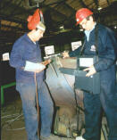 Fig 16. ISONIC can work very closed from the welding place providing the opportunity for immediate repairing of the defect
 - ISONIC can work very closed from the welding place providing the opportunity for immediate repairing of the defect (Figure 16). It is to be noted also, that ISONIC usage will extremely reduce expenses for materials: when making ultrasonic inspection there is almost no such expenses, while the similar expenses in radiography per a year are approximately equal to expenses for purchasing a new equipment [24].
The other positive effects, provided by ISONIC are:
CONCLUSION
- We hope that information about ISONIC will generate reader's interest. We think that this system can extend an arsenal of non destructive testing equipment for inspection and diagnostics of pipelines, tanks, power stations, etc.
REFERENCES
- Objectivization of the results of ultrasonic inspection of welding seams.- Defectoscopiya, Russian Acad. Sc., 1987, No. 6, pp.3-12. Soviet Journal of Nondestructive Testing (English translation of Defectoscopiya - Edited in USA), v.23, No. 6, Jun., 1987, pp. 371-379. /A.Gurvich, G.Passi
- Automation of ultrasonic inspection - where and why necessary?.- 10th World Conference on Non Destructive Testing, Moscow, 1982. Proc. v.7, pp.111-124 / G.Engl, E.Fisher, D.Figlhuber
- Lessons learned from the PISC III study of the influence of human factors on inspection reliability.- 6th European Conference on Non Destructive Testing, Nice, 1994. Proc. v.2, pp.989-993 / R.A.Murgatroyd, G.M.Worrall, S.Crutzen
- The three phases of PISC and their impact on inspection practices.- 6th European Conference on Non Destructive Testing, Nice, 1994. Proc. v.2, pp.1025-1029. / S.Crutzen, E.Borloo, R.Nichols, A.Miller
- Reducing the influence of human factors on the reliability of manual ultrasonic weld inspection. - INSIGHT - The Journal of British Institute of Non-Destructive Testing, 1995, Vol.37, N10, p.788-791., NDTnet - May 1996, Vol.1 No.05 / G.Passi, Y.Shoef and M.Kritsky
- Manufacture and Testing of Pressure Vessels: Manufacture and Testing of Joints: Non-Destructive Testing of Welded Joints.- AD-Merkblatt HP5/3, Edition July 1989.
- Acoustic coupling monitoring adapter for ultrasonic flaw detector.- Defectoscopiya, Russian Acad. Sc., 1983, No.10, pp.67-71 /A.Gurvich, G.Passi and others
- Comparison of nonautomated systems used for the acoustic nondestructive testing of welded joints.- Defectoscopiya, Russian Acad. Sc., 1991, No. 2, pp.3-9. Soviet Journal of Nondestructive Testing (English translation of Defectoscopiya), v.27, No. 2, Oct., 1991, pp.79-83 /A.Gurvich, G.Passi
- Techniques for acoustic inspection of metals.- Monogarphy,"Masinostroenie", Moscow, 1989 /N.Aleshin and others pp.184-186; 394-395
- Ultrasonic testing of welded joints.- Monogarphy,"Stroyizdat", Moscow, 1989 /V.Scherbinsky, N.Aleshin and others pp.134-136
- Technique for monitoring of acoustic coupling.- Auth.cert.574668 (USSR), BI 1977, N 36 / A.Gurvich and others
- Examination of the stability of acoustic contact in inspection with an inclined transducer.- Defectoscopiya, Russian Acad. Sc., 1988, No.3, pp.69-78. Soviet Journal of Nondestructive Testing (English translation of Defectoscopiya - Edited in USA), v.24, No. 3, Nov., 1988, pp. 203-211. / G.Passi
- Comparison of appraisal methods for an acoustic contact.- Defectoscopiya, Russian Acad. Sc., 1988, No. 4, pp.71-79. Soviet Journal of Nondestructive Testing (English translation of Defectoscopiya - Edited in USA), v.24, No. 4, Dec., 1988, pp. 281-288. /G.Passi
- Technique for ultrasonic inspection.- Auth.cert.1534388 (USSR), BI 1990, N 1 /G.Passi
- Lund S.A., Jensen P.R. Method and apparatus for ultrasonic examination.- Pat.3939697 (USA), Issue Date 1976, 02, 24
- Recorder SD-22. Operating manual.- Kishinev, VNIINK, 1981 /D.Sirota
- A laboratory mock-up ultrasonic system for composites.- Materials Evaluation, 1982, Vol.40, N 7, p.756-761 / F.Chang and oth.
- Increasing sensitivity of ultrasonic equipment.- Defectoscopiya, Russian Acad. Sc., 1986, No.3, pp.13-20 /D.Sirota and others
- Ultrasonic flaw detector.- Auth.cert.1337758 (USSR), BI 1987, N 34 /G.Passi and A.Firsukov
- Ultrasonic flaw detector.- Auth.cert.1388786 (USSR), BI 1988, N 14 /A.Gurvich and G.Passi
- Digital depth-measurer for ultrasonic flaw detector.- Defectoscopiya, Russian Acad. Sc., 1991, No. 3, pp.83-85. Soviet Journal of Nondestructive Testing (English translation of Defectoscopiya - Edited in USA), v.27, No. 3, Nov., 1991; Pat. 1337758 (Russia), 1987. /G.Passi and others
- New defect recording system.- INSIGHT - The Journal of British Institute of Non-Destructive Testing, 1996, Vol.38, N4, p.260 / G.Passi
- I2-Sonic - vollständige Dokumentation dank kontinuierlicher Aufzeichnung der Prüfkopfbewegung und Ankopplung bei der manuellen Schweißnahtprüfung.- DGZfP Jahrestagung 1997 - Zerstörungsfreie Materialprüfung, Dresden, 5. - 7. Mai 1997 / [62] M. Berke, W.-D. Kleinert
- The commercial role of NDT in the context of a changing world.- INSIGHT - The Journal of British Institute of Non-Destructive Testing, 1994, Vol.36, N5, p.334-341 / D.Wells