

|

|
Reducing the influence of human factors on the reliability of manual ultrasonic weld inspection
Garri S. Passi, Yossi Shoef, Marina V. Kritsky
Abstract
- Being under influence of human factors the low cost manual ultrasonic testing of welded joints can't compete with the expensive and hazardous X-ray or isotope inspection in many cases, despite the advantage of having highest sensitivity. To minimize such influence special exploration was performed and new I²-Sonic Manual Ultrasonic Testing Objectivization System was created. The main I²-Sonic concept is automatic on-line imaging and documenting two kinds of NDT data including operator's observing testing technology and his mistakes, and quality of object under test. Exploration results, I²-Sonic principles, and some other new concepts are discussed in the paper.
Table of contents
INTRODUCTION
- Manual ultrasonic testing of welded joints is in wide-spread use in industrial applications, mainly for the most common cases (more than 70%) where the length of the welded joints is shorter than 1m and the sole practical solution is manual inspection. [1,2]The conventional manual ultrasonic testing has the following important demerits:1. Inspection results are essentially dependent on the operator's actual performance of the testing in the field, his observation of the indications, and his own on the spot interpretation.2. Oscilloscopic indications (A-scan images) of the flaw echoes are non obvious for welding personnel and for users of the products with welded joints.Due to these deficiencies and despite the advantage of having the highest sensitivity, the low cost ultrasonic testing can't compete with the expensive and hazardous X-ray or isotope inspection in many cases. The presented paper contains some new concepts of exploration factors of human unreliability in manual ultrasonic testing and reducing their influence on the inspection results.
EXPLORATION HUMAN FACTORS AND REDUCING THEIR INFLUENCE ON THE TEST RESULTS
- It is easy to understand that all of three stages of manual ultrasonic inspection such as calibration equipment, detection defects in the object under test, and data reporting are under the influence of human factors and there are two general ways to reduce this influence: [3,4,5,6]
- To eliminate as much as possible operator's mistakes and to indicate them during the observing inspection and in the inspection report automatically created by special additional devices.
- To ease inspection procedures using additional technique that helps operators to observe inspection properly.
CALIBRATION VARIABILITY
- The most significant factor of calibration variability is the deviation from needed calibration gain: mainly it is 2 to 3dB but the deviations up to 13dB were registered with increasing operators' tiredness and worsening test environmental conditions [5]. Today the gain deviation and other calibration mistakes are easy detectable if a new generation ultrasonic instrument giving output of the calibration file is applied (for example, USK-7D, USN-50 by Krautkramer-Branson, EPOC-III by Panametrics or similar). The above mentioned instruments also allow to reduce possibility of calibration mistake by memorizing great number of calibration files and loading them in any time.In addition to the gain deviation the DAC curve calibration mistake can reduce reliability of the test results. Regularly DAC curve is calibrated by getting echoes from conventionally equal reference reflectors using the different distances between ultrasonic probe and reflector. It takes a lot of time and operator's concentration to perform DAC curve calibration properly. As we have obtained, the deviations up to 12dB are possible here. To ease DAC curve calibration and to minimize possibility operator's mistakes a very simple DAC Calibration Adapter is proposed (Fig.1).
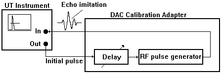
It creates RF pulse that imitates echo having fixed small amplitude and being adjustably delayed from ultrasonic instrument's initial pulse in wide time range. To use DAC Calibration Adapter the ratio between reference reflectors' echoes and coordinates of these reflectors have once to be defined using test blocks. After that DAC Calibration Adapter allows easy to create DAC curve without using any test block providing reducing deviation to value up to 1 dB only (Fig.2).
| Fig 2. Example of the DAC Calibration Adapter Operating Chart | |
| DAC curve calibration chartThis calibration chart is based on using the DAC Calibration Adapter. The DAC curve must be created using imitations of echoes from three reflectors that have amplitudes U1, U2, U3 and coordinates D1, D2, D3. U1/U2=6dB; U1/U3=11dB; U2/U3=5dB Reflectors' coordinates: D1=7mm; D2=38mm; D3=75mm * Zero of the UT instrument's digital depth meter must be previously calibrated * Sweep Delay must be adjusted equal to Zero * Sweep Range must be adjusted to 80mm | |
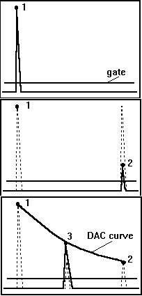 | Step1. Connect DAC Calibration Adapter to the UT instrument and manipulate its delay regulator to get the 7mm UT instrument digital distance indication. Adjust amplitude of the indicated pulse to the 100% of the screen height. Mark the top of the pulse as a point 1 of the DAC curve. Step2. Change the delay of DAC Calibration Adapter to get the 75mm UT instrument digital distance indication. Reduce the Gain of UT instrument in 11dB. Mark the top of the pulse as a point 2 of the DAC curve. Step3. Change the delay of DAC Calibration Adapter to get the 38mm UT instrument digital distance indication. Increase the Gain of UT instrument in 5dB. Mark the top of the pulse as a point 3 and create DAC curve. |
DETECTION UNRELIABILITY
- Missing obliged predefined trajectory of the probe movement over the object under test.
- Violations of the acoustic coupling.
- Inattention to the received echoes.
- Traditional ultrasonic instrument indicators (screen+alarm) only.
- On-line alarming violations of the acoustic coupling as an addition to the standard indicators.
- On-line imaging probe trajectory and on-line alarming violations of the acoustic coupling as an addition to the standard indicators.
- monitoring probe coordinates on the object under test (probe location)
- monitoring acoustic coupling
- ultrasonic data processing superimposed to the probe location and acoustic coupling data with image memorizing
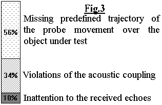 There are three human factors defining detection unreliability:[3,4]
and their relative magnitudes in the lacking defects cases). According to obtained results the easy understandable on-line imaging two kinds of NDT information is proposed to reduce detection unreliability (Fig.4).
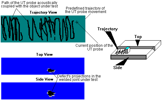
Such presentation completely indicates operator's observing testing technology and his mistakes showing the path of ultrasonic probe acoustically coupled with the object under test. It is the first kind of NDT data. In the most cases where there is no defects in the object under test it is unique evidence of the inspection.The proposed imaging also excludes the factor of inattention to the received echoes, because the defect's projection imaging is automatically observed when the probe crosses the areas of the receiving defects' echoes. Defect's projections to the Top and Side sections of the welded joint present the second kind of NDT data: quality of object under test.To provide such presentation of the inspection results the following issues must be completed:
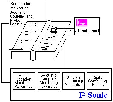
Fig. 6a,6b Options of the I²-Sonic probe trajectory imaging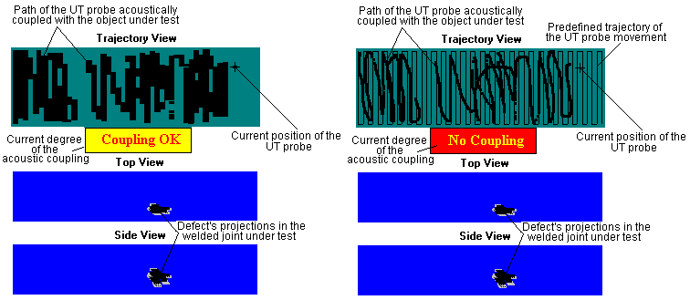
- On-line imaging two kinds of NDT data as it is described above and presentation this information in the inspection report.
- Un-violation the probe manipulation regular for operators. For this purpose non contact air acoustic probe location is used to measure probe coordinates and additional low frequency noise acoustic vibrator is installed on the object under test near the probe movement area [7] to create the reference signal for monitoring acoustic coupling. It means that any standard ultrasonic equipment can be used and any standard ultrasonic probe can be voluntarily manipulated.
- Providing comfortable operating. The scalable (true type) real time imaging of the probe movement trajectory realized by operator's hand (Fig.4) gives to operator the possibility to check his own manipulations and to correct them, if it is necessary, during the inspection procedure. But on this image there is no data about obliged trajectory that must be performed and it is difficult to evaluate quickly the current state of the testing technology observing. Because of this factor and taking in account that all his manipulations are recorded operator must reduce the testing speed. To obviate this disadvantage the I²-Sonic technology provides two options that are illustrated by Fig.6. According to the first option (Fig.6a) the background imaging of the obliged trajectory is provided. According to the second option (Fig.6b) the width of the lines imaging probe movement is proportional to effective width of ultrasonic beam enabling maximal possible step of the probe movement. In this case the maximal speed together with the inspection technology observing are provided. Both options also provide on-line indication current degree of the acoustic coupling. Using such options operator can concentrate all his attention only on the painting background image providing acoustic coupling and correct probe movement.
- Compensating influence of the acoustic coupling deviations on the defects' video imaging if the current degree of acoustic coupling is not ideal but it is enough in order to continue ultrasonic examination providing its sensitivity. For this purpose the current level of reference signal received by ultrasonic probe is additionally compared with its maximal value stored during the calibration. If the current level of reference signal is less than its maximal value but more than critical threshold level then current deviation of reference signal is measured and updating current values echo's amplitude is supplied. With such option defects's images will be approximated to the ideal acoustic coupling conditions (Fig.7).
Fig.7 I²-Sonic defects' image updating
Not updated defect's projection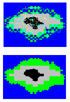
Updated defect's projection - Square of the area between probe and object under test filled by couplant. To provide stability of the coupling area's square a standard ultrasonic probe can be equipped by easy-to-lock system that provides acoustic coupling using magnetic liquid [9].
- Thickness of the coupling layer. Deviation of this thickness is inevitable for manual probe manipulations and its influence is efficiently determined by acoustical impedance of the probe prism and couplant (Fig.8). To minimize effect of the layer thickness deviation the couplant impedance must be as much as possible approached to the complex impedance of the probe prism.
| The main principles of I²-Sonic technology are: |
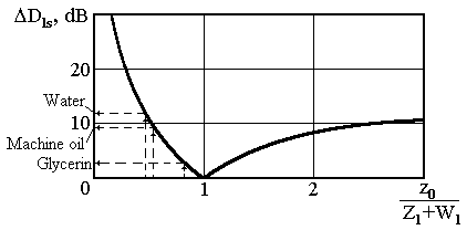 | Fig. 8 Influence of the coupling layer fluctuations on deviation DDls of the energy's transparency "probe prism to object under test" as a function of the couplant impedance z0 (Z1 - complete impedance of the probe prism for longitudinal waves; W1 - complete impedance of the probe prism for shear waves) |
It is easy to see that described I²-Sonic options provide obvious elimination operator's mistakes in the inspection procedure.
ADDITIONAL MEASUREMENTS AND DATA REPORTING
- According to presented I²-Sonic concepts the manual ultrasonic inspection data report must consist of at least two automatically created obliged parts:
- calibration report presenting all the calibration data;
- detection report presenting imaged observing testing technology and quality of object under test.
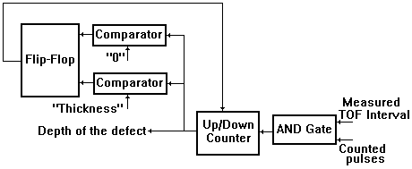
Generally, the third part of the inspection report can consist of additionally measured results plotted as much as possible automatically. To eliminatehuman mistakes in the additional measurements ultrasonic instrument must be equipped by utilities providing direct or trick easing measurement procedures.We consider that human created interpretation and conclusion must be placed in the last part of the manual ultrasonic inspection data report. Having objective automatically created presentation of calibration data, detection data, and additional measurements' data the level III specialist can interpret results obtained in the field observing, if it's necessary, postprocessing in the laboratory environment. His own conclusion about observing testing technology and quality of object under test based on the objectively obtained and presented data will grow reliability of the inspection results.
CONCLUSIONS
- The most efficient way of increasing reliability of manual ultrasonic inspection is on-line imaging and automatic documenting two kinds of NDT data such as observing inspection technology and quality of object under test.
- Observing inspection technology is completely determined by reporting calibration data and imaging the path of ultrasonic probe acoustically coupled with the object under test. In the most cases where there is no defects in the object under test it will be unique objective evidence of the inspection. The quality of object under test preferably have to be presented by projection flaw imaging.
- To eliminate human mistakes in all inspection procedures (calibration, detection defects, additional measurements) ultrasonic instruments and inspection technologies must be equipped by utilities providing direct or trick easing measurement procedures. All additional devices applied for probe location, monitoring acoustic coupling etc. must not violate probe manipulation procedures regular for operator.
REFERENCES
- Objectivization of the results of ultrasonic inspection of welding seams.- Defectoscopiya, Russian Acad. Sc., 1987, No. 6, pp.3-12. Soviet Journal of Nondestructive Testing (English translation of Defectoscopiya - Edited in USA), v.23, No. 6, Jun., 1987, pp. 371-379. /A.Gurvich, G.Passi
- Automation of ultrasonic inspection - where and why necessary?.- 10th World Conference on Non Destructive Testing, Moscow, 1982. Proc. v.7, pp.111-124. /G.Engl, E.Fisher, D.Figlhuber
- MUTOS: Equipment for increasing the reliability of ultrasonic weld inspection.- International conference: Advanced technologies in welding and non-destructive examination. Proc., Tel-Aviv, 1993, pp.32-34. /G.Passi, S.Passi
- Comparison of nonautomated systems used for the acoustic nondestructive testing of welded joints.- Defectoscopiya, Russian Acad. Sc., 1991, No. 2, pp.3-9. Soviet Journal of Nondestructive Testing (English translation of Defectoscopiya - Edited in USA), v.27, No. 2, Oct., 1991, pp.79-83 /A.Gurvich, G.Passi
- Lessons learned from the PISC III study of the influence of human factors on inspection reliability.- 6th European Conference on Non Destructive Testing, Nice, 1994. Proc. v.2, pp.989-993. /R.A.Murgatroyd, G.M.Worrall, S.Crutzen
- The three phases of PISC and their impact on inspection practices.- 6th European Conference on Non Destructive Testing, Nice, 1994. Proc. v.2, pp.1025-1029. /S.Crutzen, E.Borloo, R.Nichols, A.Miller
- Comparison of appraisal methods for an acoustic contact.- Defectoscopiya, Russian Acad. Sc., 1988, No. 4, pp.71-79. Soviet Journal of Nondestructive Testing (English translation of Defectoscopiya - Edited in USA), v.24, No. 4, Dec., 1988, pp. 281-288. /G.Passi
- Examination of the stability of acoustic contact in inspection with an inclined transducer.- Defectoscopiya, Russian Acad. Sc., 1988, No.3, pp.69-78. Soviet Journal of Nondestructive Testing (English translation of Defectoscopiya - Edited in USA), v.24, No. 3, Nov., 1988, pp. 203-211.
- Magnetic system for ultrasonic probe providing operation with magnetic liquid coupling layer.- Defectoscopiya, Russian Acad. Sc., 1989, No.3, pp.33-39. /V.Korovin, I.Lebedev, Yu.Raykher, V.Epifanov
- Techniques for acoustic inspection of metals.- Monogarphy,*"Masinostroenie", Moscow, 1989, 456 pp. /N.Aleshin, I.Ermolov, A.Gurvich and others
- Digital depth-measurer for ultrasonic flaw detector.- Defectoscopiya, Russian Acad. Sc., 1991, No. 3, pp.83-85. Soviet Journal of Nondestructive Testing (English translation of Defectoscopiya - Edited in USA), v.27, No. 3, Nov., 1991; Pat. 1337758 (Russia), 1987. /G.Passi
List of all Figures
- DAC calibration adaptor
- Example of the DAC Calibration Adapter Operating Chart
- Factors of the detection unreliability and their relative magnitudes in the lacking defects cases
- On-line imaging two kinds of NDT information
- I2-Sonic Manual Ultrasonic Testing Objectivization System
- Options of the I²-Sonic probe trajectory imaging
- I²-Sonic defects' image updating
- Influence of the coupling layer fluctuations on deviation DDls of the energy's transparency "probe prism to object under test" as a function of the couplant impedance z0 (Z1 - complete impedance of the probe prism for longitudinal waves; W1 - complete impedance of the probe prism for shear waves)
- "Skip independent" depth meter for the UT instrument