

|

|
 | Portable Workstation for Ultrasonic Weld Inspection M.Berke, W.-D.Kleinert, J.Reinersmann, U.Schlengerman, K.VolkmannKrautkramer - Germany. M.Kritsky, V.Moshkovich, A.Passi, G.PassiSonotron NDT - Israel |
- The low probability of detection is noted as major problem of non destructive testing - this evened due to techniques which have high attainable flaw sensitivity such as conventional ultrasonic inspection, and is mainly due to the human factors [1]. The ISONIC system - introduced a few years ago to close this gap [2 - 11] - can at last ensure the validity of manual ultrasonic inspection. Based on the unique experience learned from field operations, today's rugged portable battery operated ISONIC workstation with internal ultrasonic flaw detector PC card covers almost the whole range of weld inspection tasks and requirements through an extremely wide arsenal of application software.
Principles of Operation
- the background images of required Scanning Pattern and Top and Side Views of inspected volume are created; these images stipulated by size of the weld under test and inspection parameters (Scan Index, Skip Distance, Probe Angle, etc.) keyed in by the operator
- the operator clamps ultrasonic probe into the probe holder, a hand-held portable implement
- the operator grips the probe holder while scanning according to the background image of Scanning Pattern to be observed; the pulses of ultrasonic energy are transmitted towards the weld under test, echoes reflected therefrom are detected and measured automatically
- receivers of airborne ultrasound placed on the object under test detect pulses of one or two emitters located on the probe holder; the coordinates and swiveling angle of ultrasonic probe are determined automatically through measuring travel times of airborne ultrasound
- Low frequency noise is emitted into the object under test as reference signal for pickup by probe; the degree of acoustic coupling is determined by measuring the level of received reference signal
- As a result, the following images and signals are generated:
- image of actual probe trace made with required degree of acoustic coupling and probe swiveling angle does not exceeding predefined limit - testing integrity evidence
- perceptible signals corresponding to:
- the current probe location on the object under test
- the current degree of acoustic coupling
- the current probe swiveling angle
- projection images of defects in Top View and Side View created through correlating between echoes amplitudes and travel times, probe coordinates and swiveling angle and degree of acoustic coupling
- all captured and imaged data can be stored with further representing, postprocessing, documenting and sharing
Prior to the scanning:
Scanning:
After the scanning:
Scanning Schemes
- Thanks to mechanics-free encoding of probe location and swiveling angle, any type of scanning strategy is supported to provide inspection of various welds: the operator just has to run appropriate software package and place airborne ultrasound receivers on the object under test accordingly:
| Scanning Scheme | Software Package |
 | I2-SONIC - inspection of planar butt joints, scanning from one side and above machined weld cup if actual. Weld length scanned in one shot - 160...400 mm; Frontal Resolution (Scan Index) �1 mm; Data Presentation - Actual probe trace as testing integrity evidence and defects projection images in the weld volume: Top and Side Views EXPERT - inspection of a section of butt joint with high frontal resolution (Scan Index �0.25 mm), scanning from one side and above machined weld cup if actual. Weld length scanned in one shot - 40...140 mm; Data Presentation - Actual probe trace as testing integrity evidence and defects projection images in the weld volume: Top and Side Views, B-scans |
 | SM-PIPE - inspection of a section of curved butt joint with small curvature radius (R = 40...200 mm), scanning from one side and above machined weld cup if actual. Weld length scanned in one shot - 40...2/3 pR mm; Frontal Resolution (Scan Index) �0.25 mm; Data Presentation - Actual probe trace as testing integrity evidence and defects projection images in the weld volume: Top and Side Views unfolded, Side View - real shape, B-scans |
 | NOZZLE - inspection of nozzle welds, scanning from one side. Weld length scanned in one shot - 40...400 mm; Frontal Resolution (Scan Index) �0.25 mm; Data Presentation - Actual probe trace as testing integrity evidence and defects projection images in the weld volume: Top and Side Views, B-scans T-WELD - inspection of Tee welds, scanning above web part. Weld length scanned in one shot - 40...400 mm; Frontal Resolution (Scan Index) �0.25 mm; Data Presentation - Actual probe trace as testing integrity evidence and defects projection images in the weld volume: Top and Side Views, B-scans |
 | PLCROSS - inspection of planar butt joints, scanning from both sides. Weld length scanned in one shot - 100...500 mm; Frontal Resolution (Scan Index) �1 mm; Data Presentation - Actual probe trace as testing integrity evidence and defects projection images in the weld volume and heat affected zones: Top and Side Views CIRCROSS - inspection of circumferential or spiral butt joints (curvature radius R �200 mm), scanning from both sides. Weld length scanned in one shot - 100...500 mm; Frontal Resolution (Scan Index) �1 mm; Data Presentation - Actual probe trace as testing integrity evidence and defects projection images in the weld volume and heat affected zones: Top and Side Views WSYSCAN - inspection of circumferential or spiral butt joints (curvature radius R �200 mm) made of austenitic materials using longitudinal wave angle beam probes, scanning from both sides. Weld length scanned in one shot - 100...500 mm; Frontal Resolution (Scan Index) �1 mm; Data Presentation - Actual probe trace as testing integrity evidence and defects projection images in the weld volume and heat affected zones: Top and Side Views |
 | TRANSCAN - inspection of butt joints for transversal defects, scanning from both sides of the weld or above heat affected zones and machined weld cup. Weld length scanned in one shot - 100...500 mm; Frontal Resolution (Scan Index) �1 mm; Data Presentation - Actual probe trace as testing integrity evidence and defects projection images in the weld volume and heat affected zones: Top and Side Views |
 | T-WELD - inspection of Tee welds, scanning above foot part using angle and / or straight beam probes. Weld length scanned in one shot - 40...400 mm; Frontal Resolution (Scan Index) �0.25 mm; Data Presentation - Actual probe trace as testing integrity evidence and defects projection images in the weld volume and adjacent areas: Top and Side Views, B-scans |
 | TOFD - inspection of welds using TOFD technology for data acquisition, storing and representation; creating TOFD Map whilst moving probes along or across the weld without relocation of probe positioning system |
Imaging Defects
- color of each segment of the defect image depends on corresponding echo height;
- coding of echo amplitudes over 24 dB range provided;
- segments corresponding to highest echo amplitudes overwrite existing segments. The following coloring protocols available:
- Linear - color of the segment depends on echo amplitude only; 0 dB color corresponds to echo height of 50% of the A-Scan window
- TCG normalizing - color of the segment depends on echo amplitude and TCG correction factor actual for echo received; 0 dB color corresponds to echo height of 50% of the A-Scan window
- DAC normalizing - color of the segment depends on ratio between echo amplitude and corresponding DAC point level; 0 dB color corresponds to the DAC level
- DGS normalizing - color of the segment depends on ratio between echo amplitude and corresponding DGS point level; 0 dB color corresponds to the DGS level
- multi-color scale as exiting on above example
- thermal scale
- gray scale
- Imaging based on dynamic correlation analysis between sequences of probe locations and swiveling angles and received echoes
- Raw data imaging
An example of ISONIC screen for inspection of Tee-weld, scanning above the foot part illustrates the imaging procedure:
There are two flaw imaging techniques supported:
 Some reflectors return direct echo accompanied with satellite pulses, which are easily recognized and not imaged separately if using correlation data analysis. However, numerous standards and inspection proceedings require raw data imaging, so both options are provided as illustrated above.
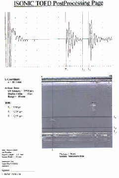
Another opportunity for capturing and storing raw data achieved through running TOFD software package, which - for the first time - allows to obtain TOFD map while mechanics-free manipulating pair of probes along or across the weld without relocating the positioning system. An example of printout of the TOFD map obtained and reconstructed A-Scan in the operator's selected section of the weld presented.
Hardware Configuration
- Initially, ISONIC was introduced as a PC-based recorder add-on to the standard ultrasonic flaw detector. The rugged industrial PC was used for field operation. Today's new generation ISONIC workstation is based on the use of the internal flaw detector PC card, for example USLT 2000. The new portable battery-operated host with sun-readable true-color touch screen allows the reduction of ISONIC dimensions and weight making it compatible with conventional ultrasonic flaw detector.
On-Line Second Opinion
 Today's ISONIC workstation can be equipped with new option for the first time allowing the transfer of A-Scans, defect images, testing performance data and instrument settings from the inspection site to the office PC, in real time via the Internet. The operator working on site (usually - level II) can now demonstrate dynamically the changing screen of his instrument to his colleague and/or boss (usually - level III) sitting at a remote site in the office and ask for a second opinion whilst actually performing the inspection and making decisions. This breakthrough enables the office PC and the on-site instrument to capture and record ultrasonic data simultaneously.To implement this option, the ISONIC workstation must be additionally equipped with a standard communication card either for mobile phone or telephone or local network and with the ISONIC Internet TV software package. The office PC must be connected to the Internet or to a local network and equipped with the same software. One office PC can collect and record data from few simultaneously working ISONICs.
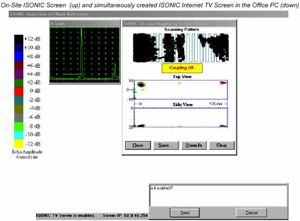 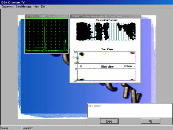 |
User's Benefits
- Image guided sequence of operation while calibrating instrument, scanning, storing and postprocessing inspection results
- High reliability of manual ultrasonic inspection achieved through guaranteed testing integrity and automatic recording of ultrasonic signals and imaging defects in real time and inspection report
- Practically proven substitute for radiography [8, 10, 12] in compliance with ASME code case 2235
- On-line second opinion feature - real time monitoring of inspection data from the office far distanced from inspection site, help to the operator in making inspection
References:
- Probability of detection. - Materials Evaluation - The Journal of American Society for Nondestructive Testing,Vol 58, No 4, 2000, p.503 - From the President / Bob Doggart, 1999-2000 ASNT President
- Reducing the influence of human factors on the reliability of manual ultrasonic weld inspection. - INSIGHT The journal of The British Institute of Non-Destructive Testing Vol 37, No10, 1995, pp. 788-791 /G.Passi, M.Kritsky, Y.Shoef
- New defect recording system. - INSIGHT - The Journal of British Institute of Non-Destructive Testing, 1996, Vol.38, N4, p.260
- Reducing the influence of human factors on the reliability of manual ultrasonic weld inspection. - Internet publication / NDTnet - May 1996, Vol.1 No.05 / issued May, 1996 / G.Passi, M.Kritsky, Y.Shoef
- Ultrasound Imaging System. - Pat. 5524627 (USA), Published, June 11, 1996 / G.Passi
- I2-Sonic vollständige Dokumentation dank kontinuierlicher Aufzeichnung der Prüfkopfbewegung und Ankopplung bei der manuellen Schweißnahtorüfung. - DGZfP Jahrestagung 1997, Zerstörungsfreie Materialprüfung, Dresden, 5-7 Mai, 1997 [62] / M.Berke and W.-D.Kleinert
- High Reliability Manual Ultrasonic Inspection. - 7 th European Conference on Non destructive testing, Copenhagen, May 26-29, 1998. Book of abstracts, p.471 / G.Passi, M.Kritsky, Y.Shoef
- High Reliability Manual Ultrasonic Inspection. - Internet publication / NDTnet - December 1998, Vol. 3 No. 12 / issued December, 1998 / G.Passi, M.Kritsky, Y.Shoef
- An Ultrasonic Imaging System. - PCT - International Application #WO99/04279, Published January, 28, 1999, 30 p. / G.Passi
- High-Reliability Manual Ultrasonic Inspection. - INSIGHT - The Journal of British Institute of Non-Destructive Testing, 1999, Vol.41, N4, p.225-231 - Cover Story, p.217 / G.Passi, M.Kritsky, Y.Shoef
- Ultrasonic Imaging System. - Pat. 5952577 (USA, Published, Sep 14, 1999) / G.Passi
- Another step forward in ultrasonic testing. - The Echo - Krautkramer Edition, No 38, July 1999, p.38-39 /E.Zimmermann